Rescue apparatus

Inactive Publication Date: 2005-08-09
CORTEZ ROSE MARY +1
View PDF21 Cites 12 Cited by
  • Summary
  • Abstract
  • Description
  • Claims
  • Application Information

AI Technical Summary

Benefits of technology

[0003]From the foregoing, it may be appreciated by those skilled in the art that a need has arisen for a life saving device that reduces an amount of effort required of the victim in using the life saving

Problems solved by technology

However, the victim may not have the strength to hold onto su

Method used


Image

  • Rescue apparatus
  • Rescue apparatus

Examples


Embodiment Construction

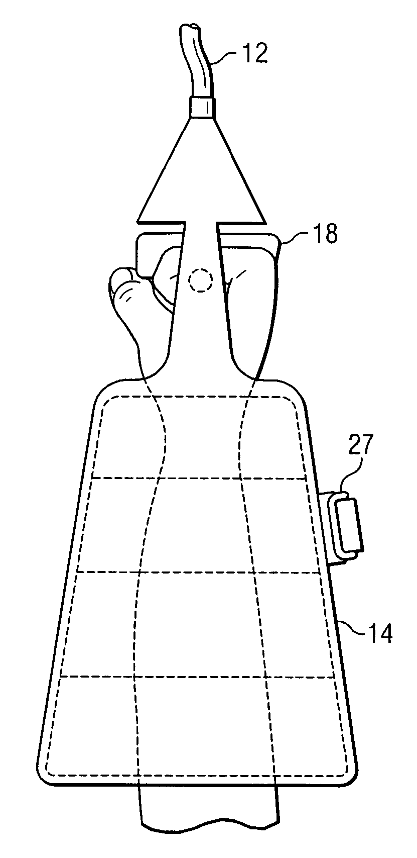
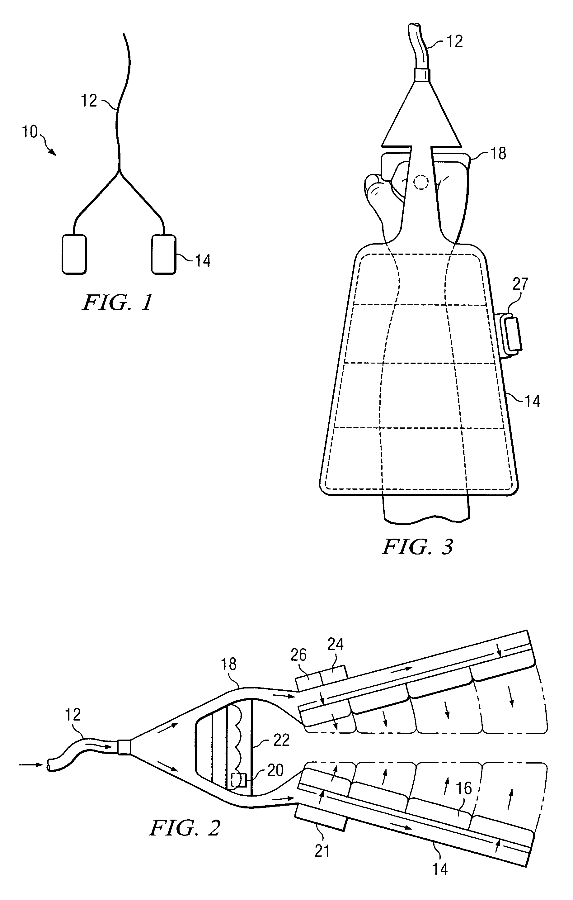
[0010]FIG. 1 is a simplified diagram of a rescue apparatus 10. Rescue apparatus 10 includes a flexible element 12 and one or more sleeve elements 14. Flexible element 12 may be a long rope or tube that may be extended out to a victim. Sleeve element 14 is fixed to or otherwise attached to flexible element 12. In operation, rescue apparatus 10 is thrown to or otherwise maneuvered towards a victim. The victim would insert an appendage into sleeve element 14 in order to facilitate a rescue or assist the victim to a safe place.

[0011]FIG. 2 is a simplified diagram of sleeve element 14. Sleeve element 14 is fixed to flexible element 12 and includes one or more pneumatic pillows 16. A handle unit 18 may also be included to connect sleeve element 14 to flexible element 12. An activation unit 20 may be a part of handle unit 18 or sleeve element 14. Activation unit 20 may allow compressed gas to flow into pneumatic pillow 16 in order to inflate pneumatic pillow 16 for the securing of sleeve e...


PUM


Abstract

A rescue apparatus includes a flexible element and a sleeve element. The flexible element may be a rope or tube used to allow the sleeve element to reach a victim. The sleeve element includes at least one pneumatic pillow. The victim inserts an appendage into the sleeve element and the pneumatic pillow is inflated to secure the appendage within the sleeve element. The victim can then be pulled to safety by the flexible element without fear that the victim would lose a grip of the sleeve element.

Description

TECHNICAL FIELD OF THE INVENTION[0001]The present invention relates in general to life saving devices and more particularly to a rescue apparatus requiring minimal effort from the victim.BACKGROUND OF THE INVENTION[0002]Many life saving devices require a victim to grab onto something and hold on until the victim can reach a safe location accessible to rescue personnel. For example, a rope or flotation device may be thrown or maneuvered into a position where a victim can reach it, hold onto it, and be pulled to safety. A rope or flotation device requires the victim to exert some effort to hold on. However, the victim may not have the strength to hold onto such devices, making it difficult to pull the victim to safety. Therefore, it is desirable to use a device that can assist in saving a victim without requiring effort from the victim.SUMMARY OF THE INVENTION[0003]From the foregoing, it may be appreciated by those skilled in the art that a need has arisen for a life saving device tha...

Claims


Application Information

Patent Timeline
IPC IPC(8): B63C9/00B63C9/13B63C9/15
CPCB63C9/155
Inventor CORTEZ, ROSE MARYVALDEZ, FERNANDO
Owner CORTEZ ROSE MARY
Why Eureka
Try Eureka