Al technical title is built by PatSnap Al team. It summarizes the technical point description of the patent document.
a technology of exercise apparatus and collapsible frame, which is applied in the direction of resistance force resistors, gymnastic exercise, stilts, etc., can solve the problems of insufficient portability and storage of the apparatus, and the available reformer does not optimally address the problem of carriage binding, so as to minimize friction between the carriage and the rails, prevent carriage binding, and facilitate transportation
Inactive Publication Date: 2005-08-09
BALANCED BODY INC
View PDF60 Cites 60 Cited by
Summary
Abstract
Description
Claims
Application Information
AI Technical Summary
This helps you quickly interpret patents by identifying the three key elements:
Problems solved by technology
Method used
Benefits of technology
[0011]The carriage assembly is captured between the rail members by roller wheel and guide roller assemblies in which four roller wheels ride on top of the rails. The guide rollers ride along the inside vertical walls of the rails to center the carriage between the rails, prevent binding of the carriage on the rail members and minimize friction between the carriage and the rails.
[0012]For storage, the rail assemblies may be telescopically collapsed, capturing the carriage between the head and foot ends, and the shoulder stops can be unlatched and folded down to make a compact package that may be rolled under a bed, stored in a closet, or easily transported in a vehicle.
Problems solved by technology
One of the difficulties, which the currently available reformers do not optimally address, is the portability and storability of the apparatus.
Method used
Image
Click on the blue label to locate the original text in one second.
Reading with bidirectional positioning of images and text.
Examples
Embodiment Construction
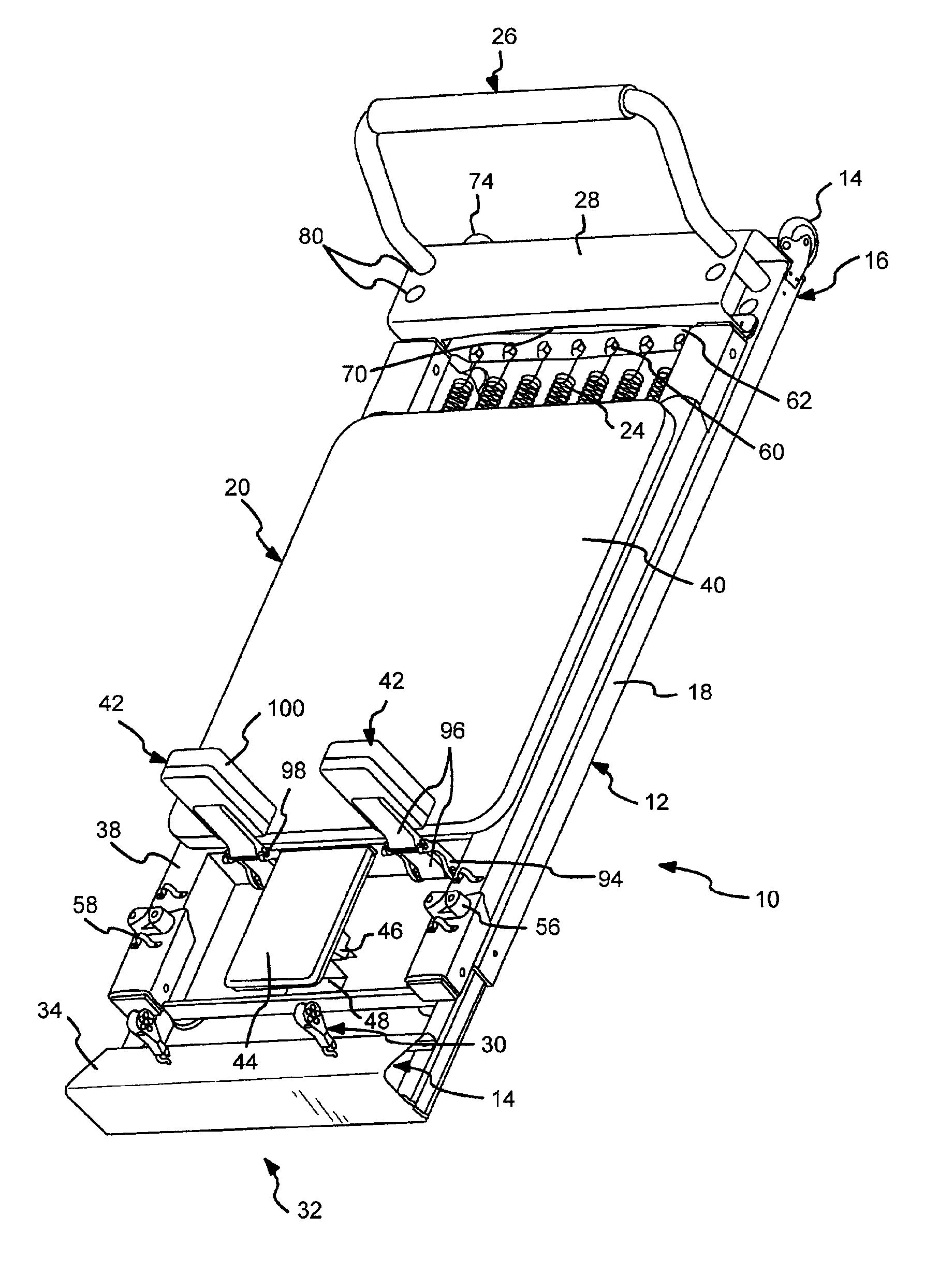
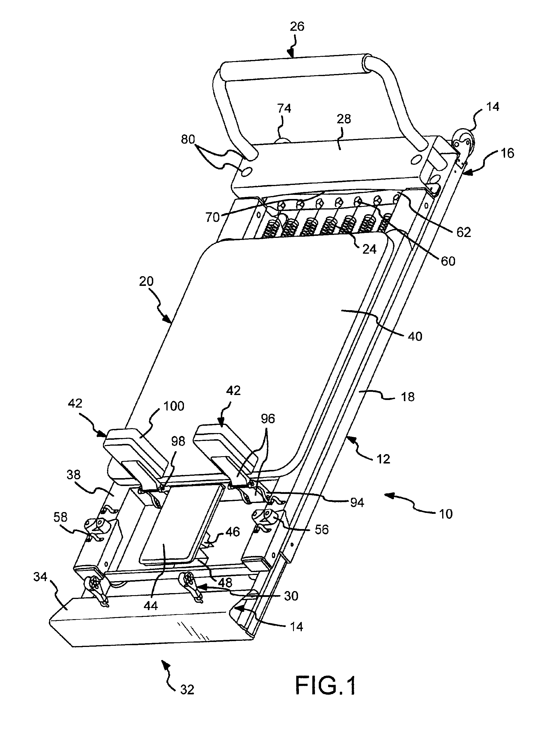
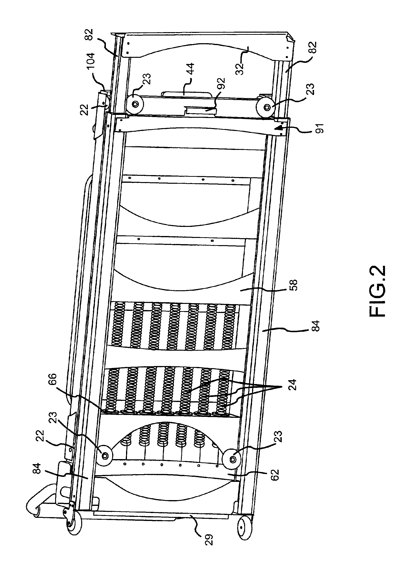
[0023]A reformer exercise apparatus 10 in accordance with a preferred embodiment of the present invention is shown in upper and lower perspective views in FIGS. 1 and 2 respectively. In these views, the reformer 10 is shown fully collapsed. The exercise apparatus 10 comprises a generally rectangular frame 12 having a head end 14 and a foot end 16 and a pair of parallel track or rail member assemblies 18 separating the head end 14 from the foot end 16.
[0024]A movable carriage 20 rides on four roller wheels 22 fastened to the underside of the carriage 20 also shown in FIG. 3. The roller wheels 22 roll on the track member assemblies 18 to support and guide movement of the carriage 20 back and forth along the track member assemblies 18 of the frame 12. Up to seven elastic members, e.g., springs 24, may be selectively connected between the carriage 20 and the foot end 16 to bias the carriage 20 toward the foot end 16 with varying amounts of spring force.
[0025]A foot bar 26 is removably f...
PUM
Abstract
An exercise apparatus comprising a generally rectangular extruded aluminum alloy frame having a head end and a foot end and including a pair of spaced apart parallel track members wherein the head end, the foot end, and the track or rail members are each formed from the metal extrusion material. The apparatus includes a movable carriage made of a rigid frame that moves along the rail members between the head and foot ends against one or more resistance members connected to the carriage and the foot end of the frame. Each of the rail members includes a longitudinal slot therein for receiving a foot support bar assembly. The rail members and head and foot end members are generally each metal tubular box extrusions and the rail members telescopically retract. Roller wheels attached to the carriage move along the top of the rail members and guide wheels move along the inside of the rail members. The invention further includes shoulder stops on the carriage that can be adjusted to a horizontal position so that the apparatus may be compactly stored.
Description
CROSS REFERENCE TO RELATED APPLICATIONS[0001]This application is a continuation in part of U.S. patent application Ser. No. 09 / 835,204, filed on Apr. 12, 2001, now U.S. Pat. No. 6,527,685, which is a continuation-in-part of U.S. patent application Ser. No. 09 / 521,555, filed on Mar. 9, 2000, now U.S. Pat. No. 6,371,895, which is a continuation-in-part of U.S. patent application Ser. No. 09 / 275,755, filed Mar. 25, 1999, now U.S. Pat. No. 6,186,929 which is also a continuation-in-part of U.S. patent application Ser. No. 09 / 266,286, filed Mar. 11, 1999, now abandoned, all four of which are hereby incorporated by reference in their entirety.BACKGROUND OF THE INVENTION[0002]1. Field of the Invention[0003]This invention relates generally to the field of exercise equipment in which a movable carriage is utilized to at least partially support a user's body, commonly referred to as a “reformer”, and more particularly to a telescopically collapsible reformer with a rigid frame carriage.[0004]2...
Claims
Application Information
Patent Timeline
Application Date:The date an application was filed.
Publication Date:The date a patent or application was officially published.
First Publication Date:The earliest publication date of a patent with the same application number.
Issue Date:Publication date of the patent grant document.
PCT Entry Date:The Entry date of PCT National Phase.
Estimated Expiry Date:The statutory expiry date of a patent right according to the Patent Law, and it is the longest term of protection that the patent right can achieve without the termination of the patent right due to other reasons(Term extension factor has been taken into account ).
Invalid Date:Actual expiry date is based on effective date or publication date of legal transaction data of invalid patent.