Electromagnetic hemming machine and method for joining sheet metal layers

a technology of hemming machine and sheet metal, which is applied in the direction of non-electric welding apparatus, electric/magnetic/electromagnetic heating, manufacturing tools, etc., can solve the problems of mechanical bending producing material deformation, destroying the integrity of the joint, and affecting the quality of the material

Inactive Publication Date: 2005-08-09
FCA US
View PDF15 Cites 28 Cited by
  • Summary
  • Abstract
  • Description
  • Claims
  • Application Information

AI Technical Summary

Problems solved by technology

All mechanical hemming operations suffer from the same problem: mechanical bending produces deformities in the materials.
Additionally, there are some quality issues pertaining to the relative positioning of the inner sheet material with respect to the outer sheet material.
In the worst case, the deformities destroy the integrity of the joint.

Method used


Image

  • Electromagnetic hemming machine and method for joining sheet metal layers
  • Electromagnetic hemming machine and method for joining sheet metal layers
  • Electromagnetic hemming machine and method for joining sheet metal layers

Examples


Embodiment Construction

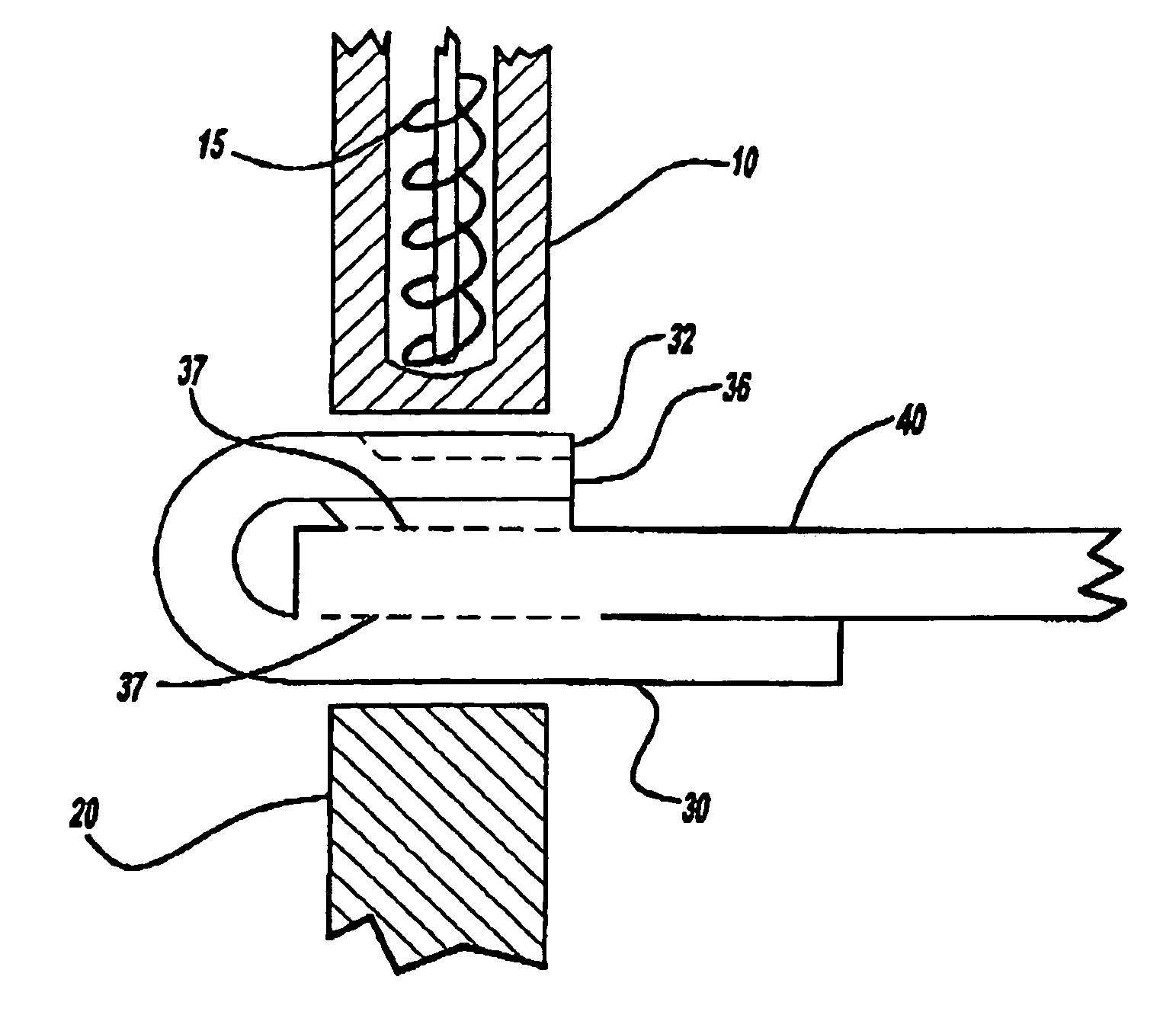
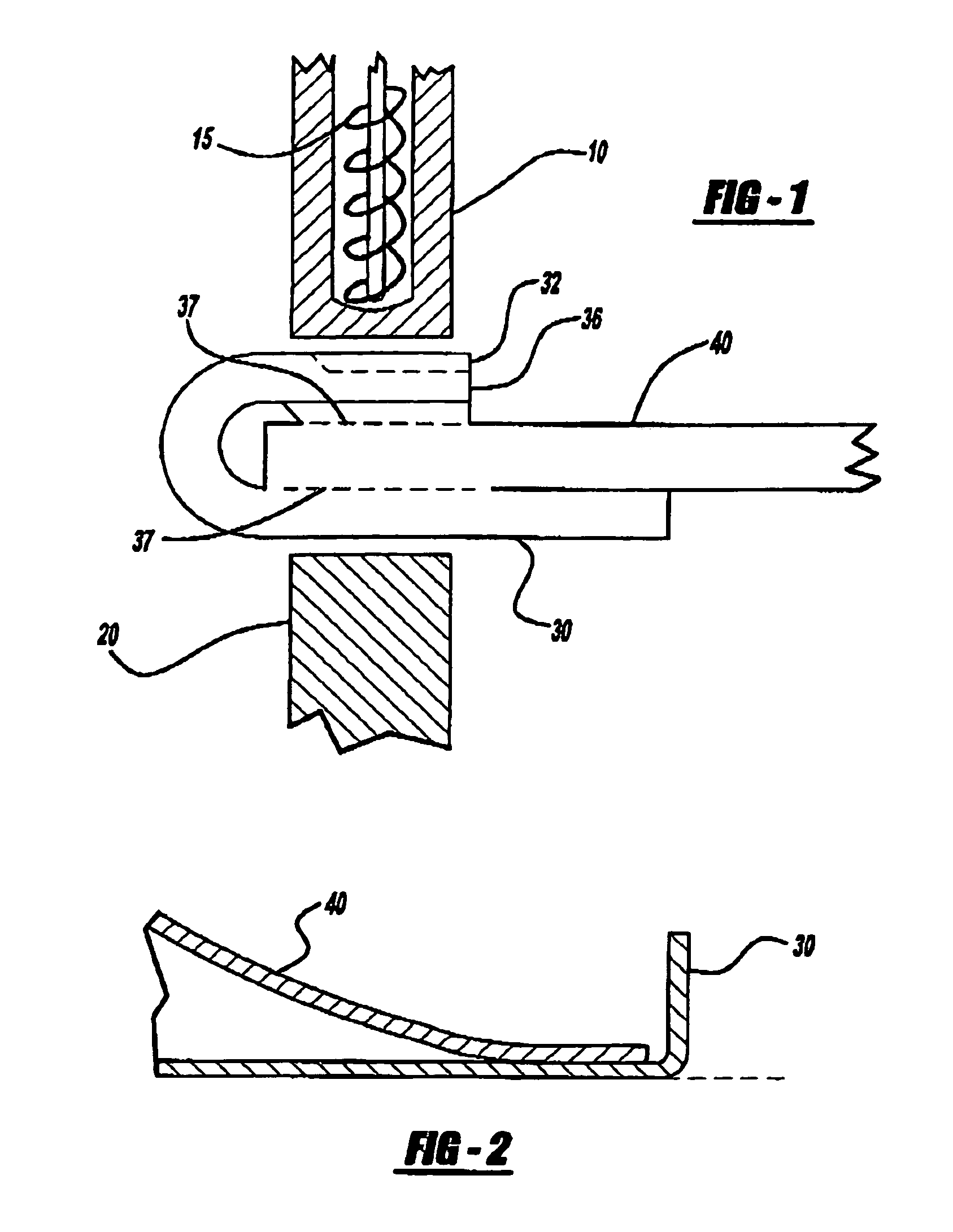
[0011]Electromagnetic forming (EMF) is based on the generation of Lorentz force, a repulsive force, that results from creating opposing magnetic fields in adjacent conductors. Generally, EMF is accomplished by directing a high current electric pulse resulting from the discharge of a capacitor bank into actuator coil. This pulse generates high intensity transient magnetic fields around the coil, which in turn induce eddy currents in a nearby, “work-piece” conductor. The work-piece conductor eddy currents are opposite to the magnetic fields around the coil which results in a repulsive force between the coil and the work-piece. A target piece is positioned on the opposite side of the work-piece from the actuator coil. The work-piece and the target piece are positioned so that the repulsive force generated by the pulse causes the work-piece to move toward the target piece at a high velocity. When the work-piece collides with the target piece, the two pieces are crimped, welded or molecu...


PUM

PropertyMeasurementUnit
forceaaaaaaaaaa
metallicaaaaaaaaaa
currentaaaaaaaaaa

Abstract

A hemming machine for joining an inner sheet metal panel with an outer sheet metal panel comprising: a hemming tool containing an electromagnetic coil positioned to electromagnetically crimp and / or weld the outer sheet metal panel to the inner sheet metal panel, where a backing die positioned outside the inner metallic sheet and the outer metallic sheet opposite the electromagnetic coil.

Description

FIELD OF THE INVENTION[0001]This invention relates to an apparatus and method for joining sheet metal. More specifically, the invention describes a hemming apparatus employing an electromagnetic driver and a method for joining sheet metal layers.BACKGROUND OF THE INVENTION[0002]Auto body components such as doors, hoods, fenders, etc. are typically formed from two pieces of sheet metal hemmed together at the peripheral edges. Hemming involves folding the edge of one panel over the edge of the other panel. Often, the hemmed sheets are also welded, soldered, glued, sealed, bolted, riveted, etc. to provide an additional connection between the pieces of sheet metal and further seal the edge to provide structural integrity and prevent migration of dirt and moisture between the joined sheets.[0003]Examples of bending and hemming machines and sealants for the hemmed panels are described in U.S. Pat. No. 5,647,243 (cam operated mechanical hemming machine), U.S. Pat. No. 5,783,298 (adhesive c...

Claims


Application Information

Patent Timeline
Patent Type & Authority Patents(United States)
IPC IPC(8): B23K20/06B23K20/22H05B6/14
CPCB21D26/14B21D39/021B23K20/06B23K20/22B23K33/002B23K2203/04B23K2203/10B23K2103/04B23K2103/10
Inventor MCCLURE, JOHN L.RAMALINGAM, SURESH C.LEZOTTE, JAMES P.
Owner FCA US
Why Eureka
Try Eureka