Surface coil decoupling means for MRI systems

a surface coil and coil technology, applied in the field of magnetic resonance imaging (mri) systems, can solve the problems of limiting the ability to move the coil, reducing the signal-to-noise ratio (snr or s/n), and reducing the capacitance between the coils, so as to achieve the limited operation and control of these mri systems

Active Publication Date: 2005-08-09
GENERAL ELECTRIC CO
View PDF16 Cites 21 Cited by
  • Summary
  • Abstract
  • Description
  • Claims
  • Application Information

AI Technical Summary

Benefits of technology

[0008]Thus, these known methods for decoupling coils restrict the design of coil arrangements (e.g., requiring coils to be adjacent to each other) in the MRI system. Therefore, the operation and control of these MRI systems is limited. For example, when designing a coil arrangement, only an overlap area that is acceptable for zero coupling may be used rather than a geometry that is optimum for imaging.

Problems solved by technology

A large coil, however, produces lower signal-to-noise ratio (SNR or S / N) if it is also used for reception, mainly because of its greater distance from the signal-generating tissues being imaged.
However, this method is limited in that it requires the coils to be adjacent to each other, thus, limiting the ability to move the coils.
However, this method introduces capacitance between the coils and significant loss of Q factor.
Thus, these known methods for decoupling coils restrict the design of coil arrangements (e.g., requiring coils to be adjacent to each other) in the MRI system.
Therefore, the operation and control of these MRI systems is limited.

Method used


Image

  • Surface coil decoupling means for MRI systems
  • Surface coil decoupling means for MRI systems
  • Surface coil decoupling means for MRI systems

Examples


Embodiment Construction

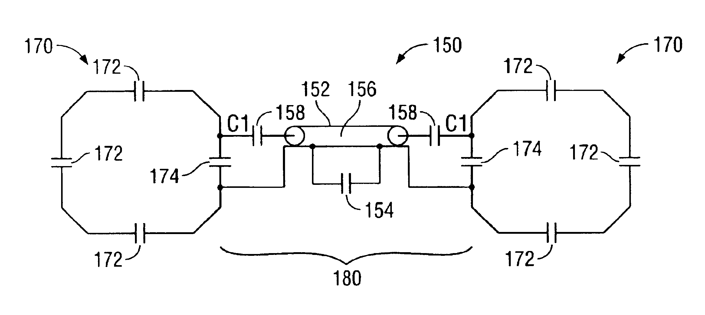
[0017]Various exemplary embodiments of the present invention provide a system and method for decoupling coils in, for example, a magnetic resonance imaging (MRI) system. For example, the various exemplary embodiments provide means for decoupling coils (e.g., a plurality of tuned surface coils) that may be adjacent each other or separated by a gap.

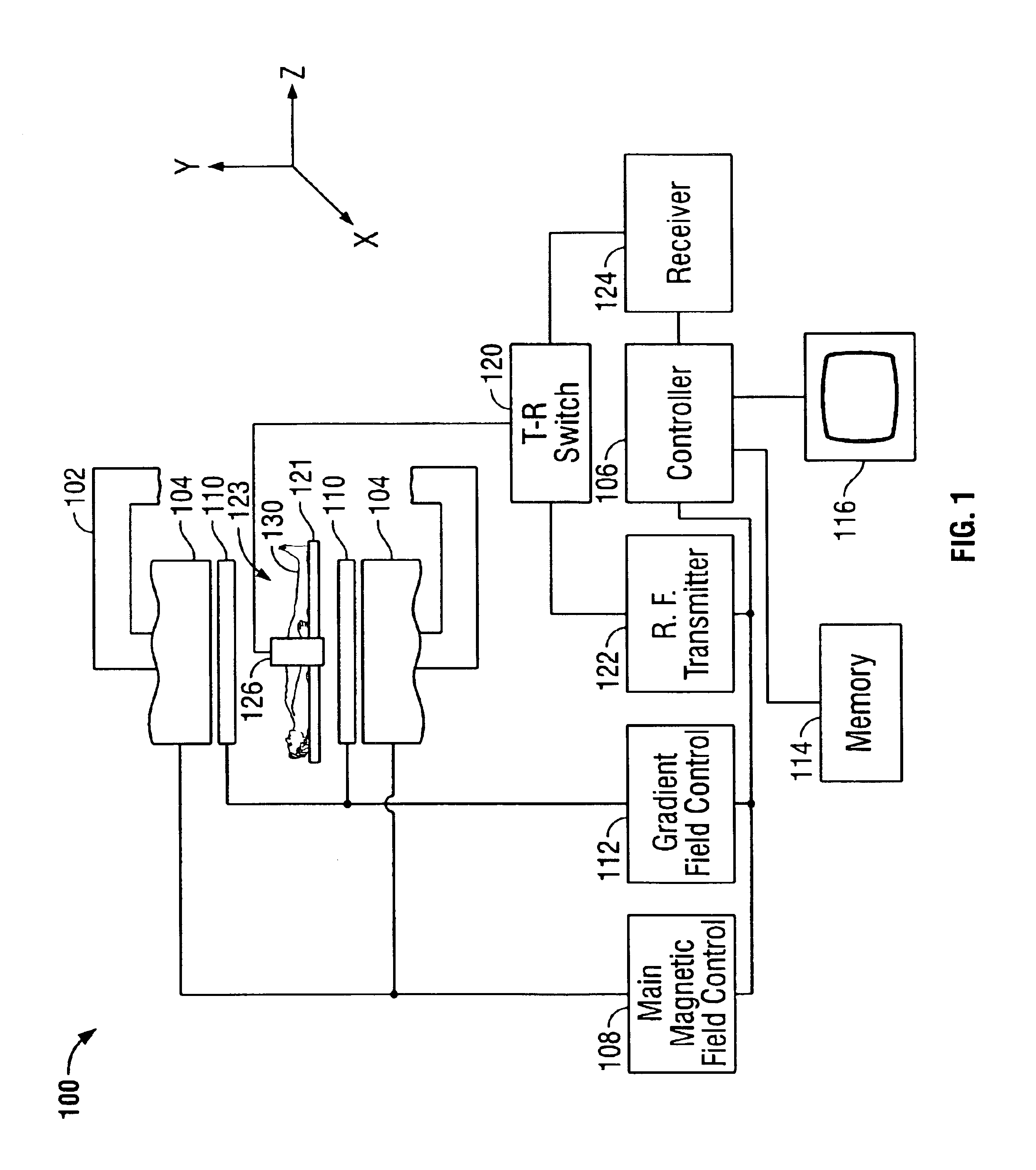
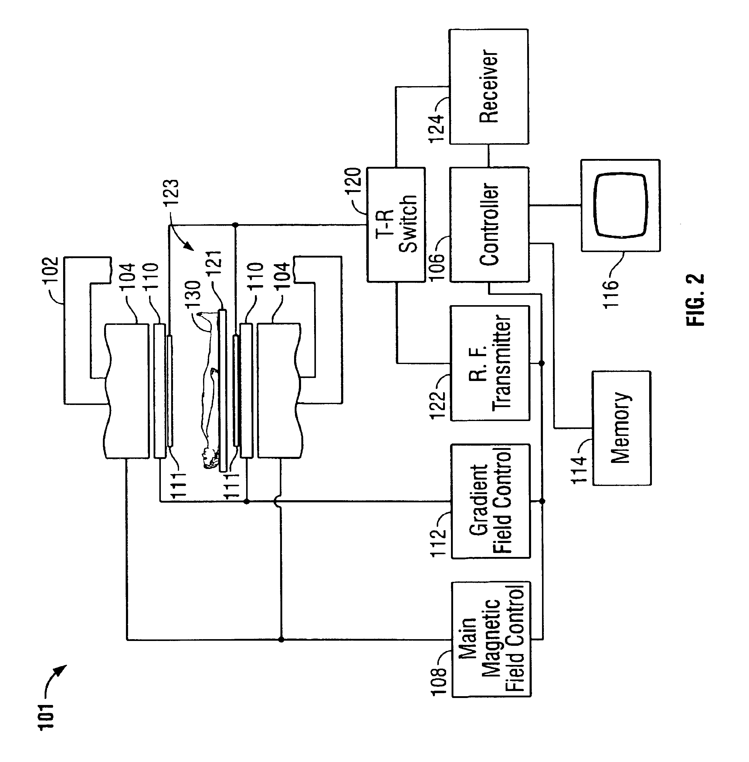
[0018]FIG. 1 is a block diagram of an exemplary embodiment of an MRI system in which systems and methods for decoupling in accordance with various embodiments of the present invention may be implemented. As shown therein, an MRI system 100 includes an electromagnet 102, pole pieces 104, a controller 106, a main magnetic field control 108, a gradient coil sub-system 110, a gradient field control 112, a memory 114, a display device 116, a transmit-receive (T-R) switch 120, a radio frequency (RF) transmitter 122, a receiver 124 and an array of detectors 126 (e.g., a cylindrical array of equally-spaced detectors). It should be noted that althou...


PUM


Abstract

A system and method for decoupling coils in a medical imaging system are provided. The coil system includes a first coil of a medical imaging system, a second coil of the medical imaging system, and a balun device connected to the first and second coils. The balun device is configured to decouple the first and second coils of the medical imaging system.

Description

CROSS REFERENCE TO RELATED APPLICATIONS[0001]This application claims priority to and the benefit of the filing date of U.S. Provisional Application No. 60 / 441,441, filed on Jan. 21, 2003 and which is hereby incorporated by reference in its entirety.BACKGROUND OF THE INVENTION[0002]This invention relates generally to magnetic resonance imaging (MRI) systems and, more particularly, to radio-frequency (RF) coils in such systems.[0003]Magnetic Resonance Imaging (MRI) utilizes hydrogen nuclear spins of the water molecules in the human body, which are polarized by a strong, uniform, static magnetic field of a magnet (typically denoted as B0—the main magnetic field in MRI physics). The magnetically polarized nuclear spins generate magnetic moments in the human body. The magnetic moments point or are aligned parallel to the direction of the main magnetic field B0 in a steady state and produce no useful information if they are not disturbed by any excitation.[0004]The generation of nuclear m...

Claims


Application Information

Patent Timeline
Patent Type & Authority Patents(United States)
IPC IPC(8): G01R33/3415G01R33/34G01R33/32G01R33/36
CPCG01R33/3415G01R33/365
Inventor BURL, MICHAELZOU, MARK XUEMING
Owner GENERAL ELECTRIC CO
Why Eureka
Try Eureka