Gear box apparatus

a gear box and gear box technology, applied in the field of gear boxes, can solve the problems of large amount of energy not being used to direct move vehicles and machine tools, inefficient systems, and excessive fuel consumption, and achieve the effect of increasing maneuverability and saving additional energy

Inactive Publication Date: 2008-02-28
ABRAMOV VLADIMIR
View PDF24 Cites 6 Cited by
  • Summary
  • Abstract
  • Description
  • Claims
  • Application Information

AI Technical Summary

Benefits of technology

[0008]I have invented a gear box and system that more efficiently converts momentum and engine or motor power to speed in vehicles and machine tools to dramatically increase fuel and electricity efficiency. The gearbox includes a sufficient number of gearsets arranged to provide a sufficient number of torques and overdrive speeds to at least one drive shaft to reduce the power generated from a motor to generate a conventional range of vehicular and machine tool speeds to less than 50 percent that of conventional motors.
[0010]I have also invented a system that significantly increases fuel efficiency of motor vehicles. This system includes a gearbox with a sufficient number of gearsets arranged to provide a sufficient number of torques and overdrive speeds to at least one drive shaft to reduce the power generated from a motor to generate a conventional range of vehicular speeds or operating machine speeds to less taan 50 percent that of conventional motors, and a motor sufficient to supply a relatively constant amount of power to the gearbox.
[0011]One embodiment of the invention is the use of gearsets that are arranged in geometric sequences to transmit mutually definite units of energy (MDU) similar to what is taught in U.S. Pat. No. 7,191,676. Each MDU gearbox design with FEES keeps highest torque of power source shaft in its work process. This dramatically cuts energy and emissions in the crafts and machine tools by limiting or eliminating need for the acceleration system and manual operation. The FEES reduces the power needed from each power source from its highest revolution to idle revolution ratio of its shaft. Thus, conventional ranges of speed and rates of acceleration can be achieved with significantly less fuel consumption. In some embodiments, motors able to produce 500 horsepower (hp) may be replaced with motors able to produce less than 100 hp with little if any loss in speed or acceleration capabilities. In other embodiments, motors able to produce 250 hp may be replaces with those able to produce less than 25 hp without significant loss of speed or acceleration.
[0012]Since some embodiments of MDUFEE gearbox family have less number of gears and shafts than comparable conventional transmissions and significantly less fuel consumption, it is advantageous to install my gearbox system in cases where vehicles have previously relied only on conventional motors and transmissions or gearboxes to generate and convert power to motion of drive shafts. Vehicles that may benefit include huge ones such as, for example, locomotive, helicopter, ship, submarine as well an consumer automobiles. Embodiments of this system are also useful for motors powered by a variety of fuels including gasoline, diesel, steam, and electricity.
[0014]Other useful embodiments are ones where a compound MDUFEE gearbox family is used. The gearbox has two to three output shafts that drive front wheels, rear wheels or all wheels on a part-time basis. These embodiments allow for more opportunity to use a vehicle in off-road environments and to save additional energy on uphill and downhill segments of travel. The compound MDUFEE gearbox family with multiple output shafts could replace the operation systems and drives of current air and sea craft to substantially increase craft maneuverability.

Problems solved by technology

Present engines and motors operate to move land, sea and air vehicles and parts of machine tools in a manner that consumes an excessive amount of fuel and electricity.
As a result, a large amount of energy is not used to directly move a vehicle and parts of machine tools.
Large industries were built with vehicles and machine tools powered by systems that were inefficient.

Method used


Image

  • Gear box apparatus
  • Gear box apparatus
  • Gear box apparatus

Examples


first embodiment

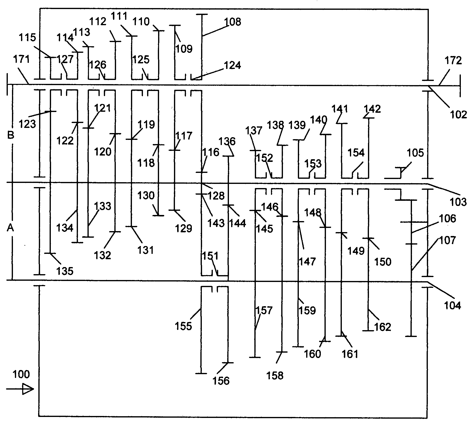
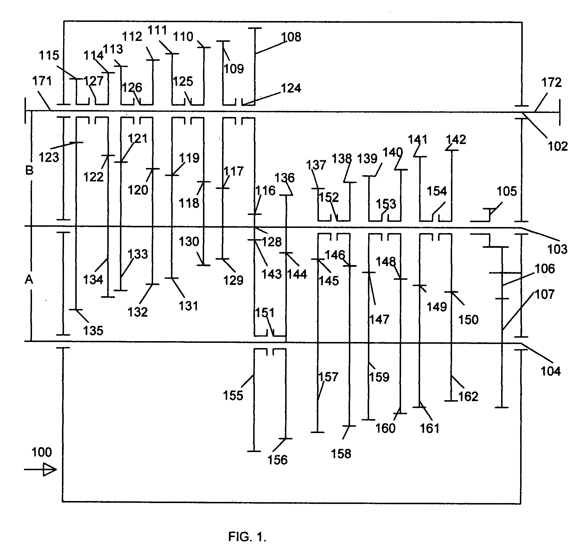
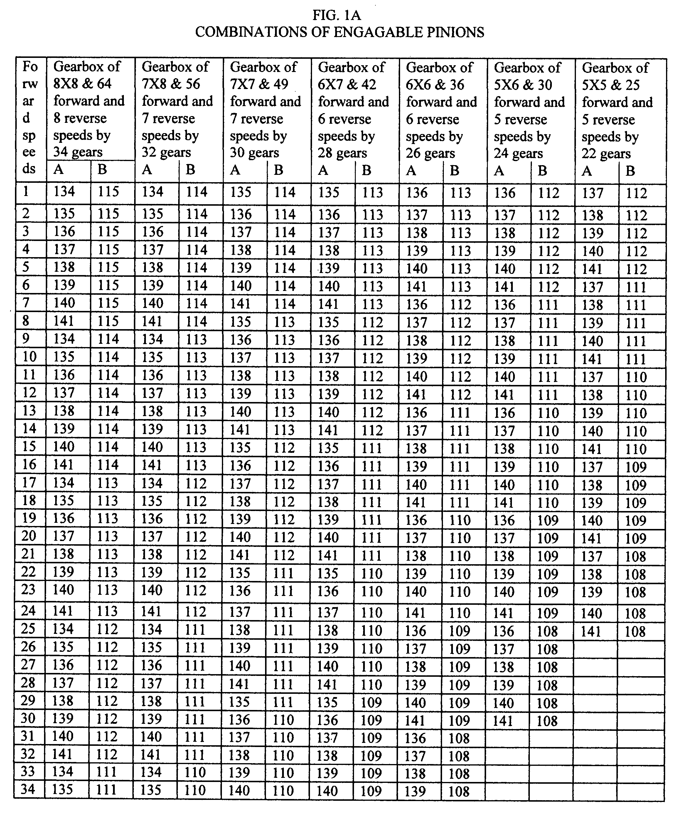
[0066]In the first embodiment shown in FIG. 1 there are 64 gears of forward included 24 overdrive speeds and 8 reverse speeds available from MDUFEE gearbox family 100 of mathematical gearbox formula 8×8. It has frame members 101 supporting drive shaft 102, intermediate shaft 103 and output shaft 104.

[0067]Power enters to left side of the MDUFEE gearbox family 100 on outward end 171 of the drive shaft 102 or on opposed outward end 172 if the shafts are reversed for using the opposite side of the gear teeth. The drive shaft 102 passes through double synchronizer clutches 123, 124, 125 and 126 with pinions 108, 109, 110, 111, 112, 113, 114, and 115 that may be separately selected. When pinions 108, 109, 110, 111, 112, 113, 114, and 115 is selected it engages drive shaft 102, and engages and turns join gear 127, 128, 129, 130, 131, 132, 133, and 134 on intermediate shaft 103 to form gearset 115, 116, 117, 118, 119, 120, 121, and 122 with ratio of 1 to R24+5, R16+5, R8+5, 1 / R0+3, 1 / R8, 1...

second embodiment

[0073]In the second embodiment, shown in FIG. 2, there are 96 gears of forward included 48 overdrive speeds and 24 reverse speeds available from MDUFEE gearbox family 200 having mathematical gearbox formula 4×4×6 in order. There are three units

[0074]MDUFEE gearbox family 200 has frame members 201 supporting drive shaft 202, first intermediate shaft 203, second intermediate shaft 204 and output shaft 205.

[0075]Power may enter the MDUFEE gearbox family 200 on the left side on outward end 271 of the drive shaft 202 or on opposite outward end 272 if the drive shaft 202 in MDU gearbox 200 is turned around for using the opposed side of teeth on the gears. A drive shaft 202 supported two double synchronizer clutches 217 and 218 with pinions 209, 210, 211 and 212 which may be separately selected.

[0076]When pinions 209, 210, 211 or 212 is selected it engages drive shaft 202, and engages and turns gears 219, 220, 221, 222, respectively, on first intermediate shaft 203 to form gearsets 213, 21...

third embodiment

[0085]In the third embodiment shown in FIG. 3 there are 108 forward and 27 reverse speeds included 36 overdrive forward and 9 overdrive reverse speeds. MDUFEE gearbox family 300 of mathematical gearbox formula 3×3×3×4 has frame members 301 supporting drive shaft 302, first intermediate shaft 303, second intermediate shaft 304, second intermediate shaft 305 and output shaft 306.

[0086]Power may enter the MDUFEE gearbox family 300 on the left side on outward end 371 of the drive shaft 302 or on opposite outward end 372 if the drive shaft 302 is turned around for using the opposed side of teeth on the gears. Power entering at outward end 371 enters single synchronizer clutch 317 with pinion 312 and double synchronizer clutch 316 have pinions 310 and 311 which may be separately selected.

[0087]When pinion 310 or 311 or 312 is selected it engages drive shaft 302, and engages and turns gear 318 or 319 or 320, respectively, on first intermediate shaft 303 to form gearset 313 or 314 or 315, r...


PUM


Abstract

A “mutually definite units of energy for forced energy economy” (MDUFEE) gearbox family has simplified the shifting pattern of shifting mechanisms to cause a real gear dependence on mechanical inertia created by the weight of a load and a fast changeable resistant force in response to the movement. This gearbox is able to operate in a manual, semi-automatic or automatic regime. Each family of designs produces torques and overdrive speeds in a faltering geometric sequence that significantly reduces the power that a motorized vehicle or craft or machine tool needs of a power source from a ratio of highest revolution of its shaft to idle revolution. This is achieved by using the unique function to keep highest torque of power source shaft within its work process. Therefore, an existing power source could be replaced by power source with substantially reduced power when gearbox of a MDUFEE gearbox family has replaced an existing gearbox. Also, the new gearbox substantially limits or eliminates the need for conventional acceleration systems to control speed produced by power source for maximizing the reduced energy consumption, emission and wear of power source. In addition, the greater degree of control of power usage with a compound MDUFEE gearbox family leads to a dramatic increase in the maneuvering capability of a motorized object on land, water or air.

Description

CROSS REFERENCE TO RELATED APPLICATIONS[0001]This application claims the benefit of PPA Appl No. 60840,665 filed Aug. 28, 2006 by the Vladimir Abramov.FIELD OF THE INVENTION[0002]This invention relates to a gearbox with gearsets having degrees of constant ratios in a geometric sequence to provide both a number of torques and a number of overdrive speeds in manual, semi-automatic and automatic regimes.BACKGROUND OF THE INVENTION[0003]There is a need for power systems to move land, sea and air transporting vehicles and machine tools with dramatically increased fuel and electricity efficiency.[0004]Present engines and motors operate to move land, sea and air vehicles and parts of machine tools in a manner that consumes an excessive amount of fuel and electricity. Currently engines and motors operate to create excessive torques that are reduced by such means as transmissions and other gear boxes to torques appropriate to turn axels or rotors at desired speeds. Acceleration systems then ...

Claims


Application Information

Patent Timeline
Patent Type & Authority Applications(United States)
IPC IPC(8): F16H3/08
CPCF16H3/093F16H3/097F16H37/043Y10T74/19167F16H2200/0065Y10T74/19242F16H2200/0017
Inventor ABRAMOV, VLADIMIR
Owner ABRAMOV VLADIMIR
Why Eureka
Try Eureka