Method and apparatus for head positioning using servo control in a disk drive

a technology of servo control and disk drive, applied in the field of disk drive, can solve the problems of reducing the accuracy of the head positioning operation, unrecorded area of servo data, and difficulty in normal head positioning operation

Inactive Publication Date: 2005-08-09
KK TOSHIBA
View PDF13 Cites 2 Cited by
  • Summary
  • Abstract
  • Description
  • Claims
  • Application Information

AI Technical Summary

Benefits of technology

[0014]The disk drive comprises a disk medium including tracks each including a data area and a servo area, and a non-servo area composed of a track not including the servo area; a head configured to execute reading or writing of data with respect to the data area or reading of servo data from the servo area; an actuator to position the head at a target track on the disk medium; and a controller which d

Problems solved by technology

The influence by this noise decreases accuracy of the head positioning operation.
However, in this method, unrecorded area of servo data equivalent to one to several tracks (referred to as a non-servo range) occurs in

Method used


Image

  • Method and apparatus for head positioning using servo control in a disk drive
  • Method and apparatus for head positioning using servo control in a disk drive
  • Method and apparatus for head positioning using servo control in a disk drive

Examples


Embodiment Construction

[0025]Hereinafter, embodiments of the present invention will be explained with reference to the drawings.

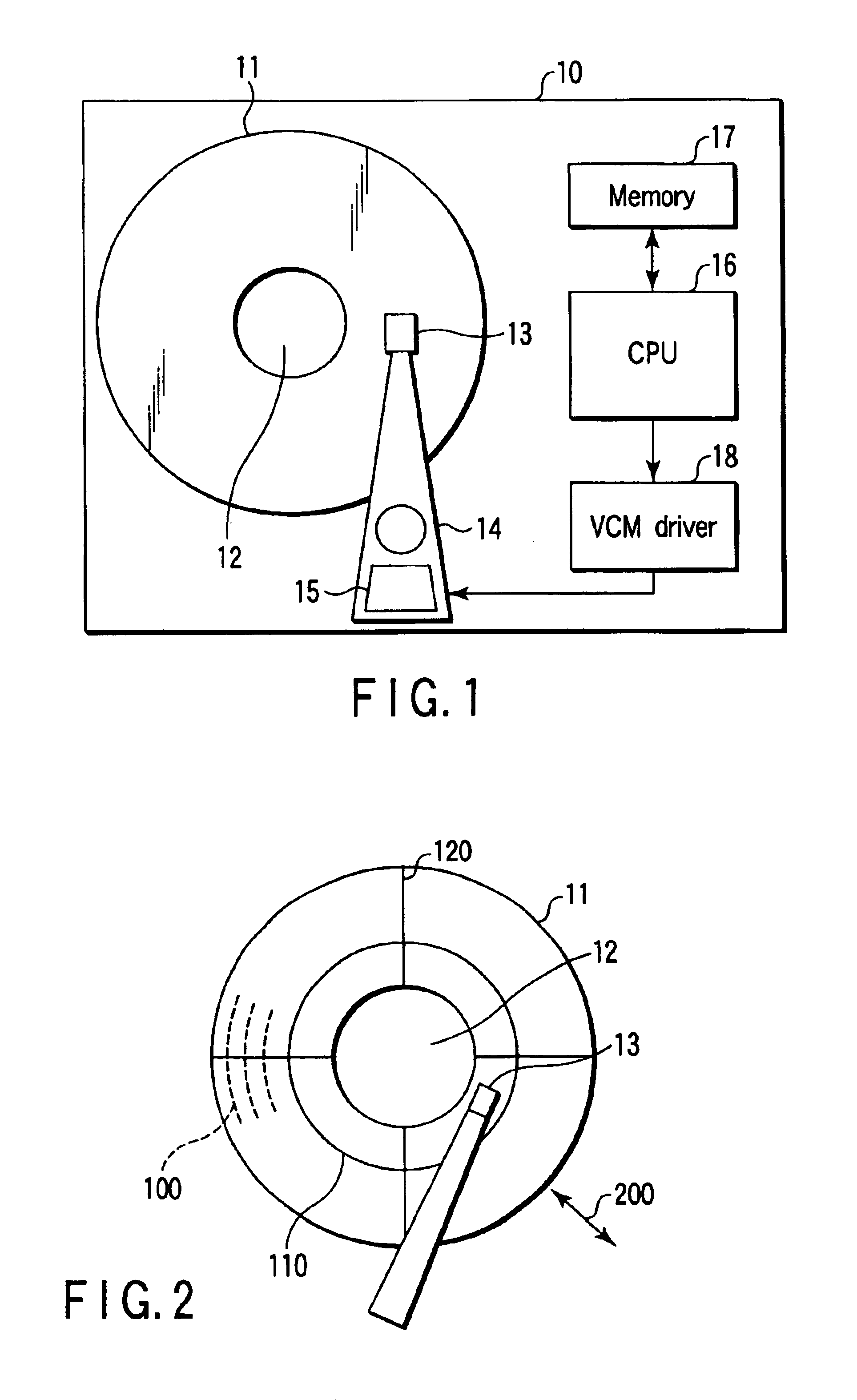
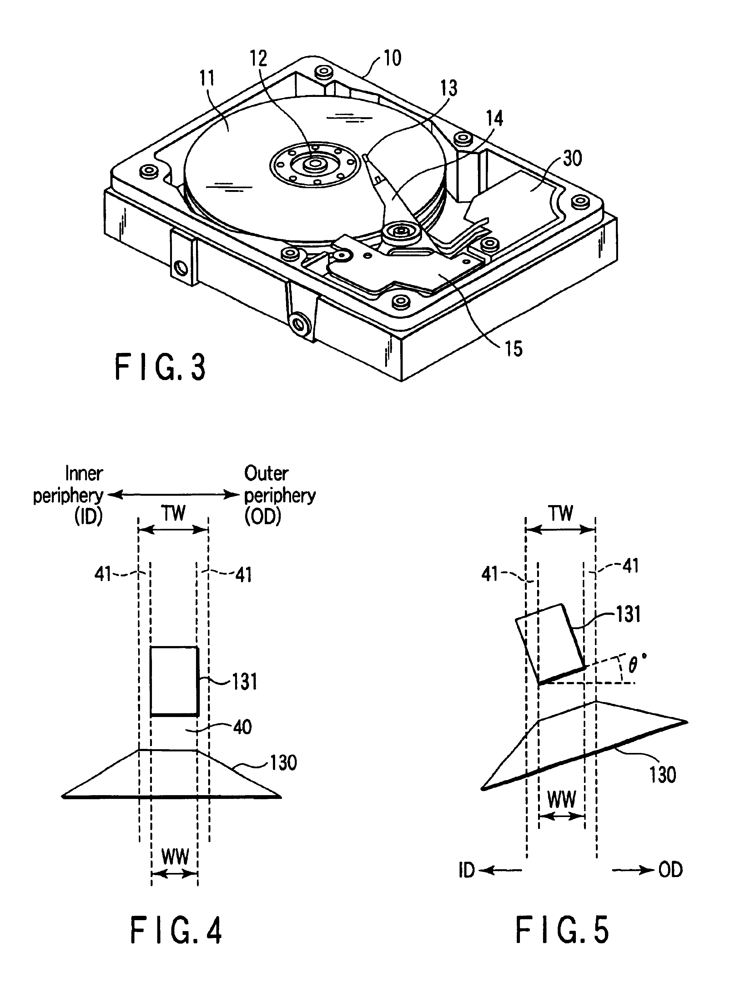
[0026]FIG. 1 is a block diagram showing a substantial part of a disk drive according to the present embodiment. FIG. 3 is a view showing an appearance of the disk drive.

(Constitution of Disk Drive)

[0027]A disk drive 10 is a hard disk drive applying, for example, a perpendicular magnetic recording method as shown in FIGS. 1 and 3, and a drive mechanism comprising a disk medium 11, a spindle motor (SPM) 12 and a rotary actuator 14 is incorporated therein.

[0028]On the actuator 14, a head 13 is mounted so as to move in a radial direction of the disk medium 11 (refer to an arrow 200 of FIG. 2) by driving force of a voice coil motor (VCM) 15.

[0029]In the head 13, a write head for writing data on the disk medium 11 and a read head for reading out data from the disk medium 11 are installed in the same slider.

[0030]In the disk medium 11, as shown in FIG. 2, a number of tracks (cylinders) ...


PUM


Abstract

There is disclosed a disk drive using a disk medium in which a non-servo range exists. In order to position a head at a target track, a CPU executes a seek operation by normal velocity control using servo data. At this positioning, when the head passes the non-servo range from which no servo data can be obtained, the CPU executes a seek operation by special velocity control to move the head at a velocity calculated based on a moving distance of the non-servo range.

Description

CROSS-REFERENCE TO RELATED APPLICATIONS[0001]This application is based upon and claims the benefit of priority from prior Japanese Patent Application No. 2003-122347, filed Apr. 25, 2003, the entire contents of which are incorporated herein by reference.BACKGROUND OF THE INVENTION[0002]1. Field of the Invention[0003]The present invention generally relates to disk drives, and particularly to servo control for head positioning using servo data.[0004]2. Description of the Related Art[0005]Heretofore, in a disk drive particularly typified by a hard disk drive, there has been incorporated a servo system in which servo data recorded on a disk medium is used to position a head at a target position on the disk medium. Here, the target position refers to a target track from which data is read out or on which data is written.[0006]Generally, servo data is recorded on a disk medium by a servo track writer in a servo writing step included in a process of manufacturing a disk drive.[0007]In the ...

Claims


Application Information

Patent Timeline
IPC IPC(8): G11B5/55G11B21/08
CPCG11B5/5526
Inventor YANO, KOJI
Owner KK TOSHIBA
Why Eureka
Try Eureka