
Hydraulically compensated stabilizer system

a stabilizer and hydrophilic technology, applied in the direction of shock absorbers, mechanical equipment, transportation and packaging, etc., can solve the problems of complicated installation of stabilizer members

Inactive Publication Date: 2005-08-16
ILLINOIS TOOL WORKS INC
View PDF72 Cites 29 Cited by
  • Summary
  • Abstract
  • Description
  • Claims
  • Application Information

AI Technical Summary

Benefits of technology

[0005]The present technique provides a stabilizer system comprising a plurality of piston cylinder assemblies, which have multiple interconnected chambers to provide cross compensation between suspension members coupled to those piston cylinder assemblies. The piston cylinder assemblies may have two or more chambers separated by pistons, which move in response to a load imposed on the suspension member coupled to that piston cylinder assembly. As the piston moves in response to movement of the corresponding suspension member, a fluid pressure is transmitted to another suspension member to distribute the load between the two suspension members. For example, the present technique may balance a load caused by maneuvering the vehicle between left and right suspension members or it may balance load caused by acceleration or deceleration between front and rear suspension members. Accordingly, the present technique is applicable to any vehicle having movable suspension members, including all sorts of automotive vehicles, motorcycles, bicycles, agricultural vehicles, public transportation vehicles, and any other suitable application.

Problems solved by technology

Installation of the stabilizer members is also complicated due to dimensional variations between vehicles and the suspension members.

Method used


Image

  • Hydraulically compensated stabilizer system
  • Hydraulically compensated stabilizer system
  • Hydraulically compensated stabilizer system

Examples


Embodiment Construction

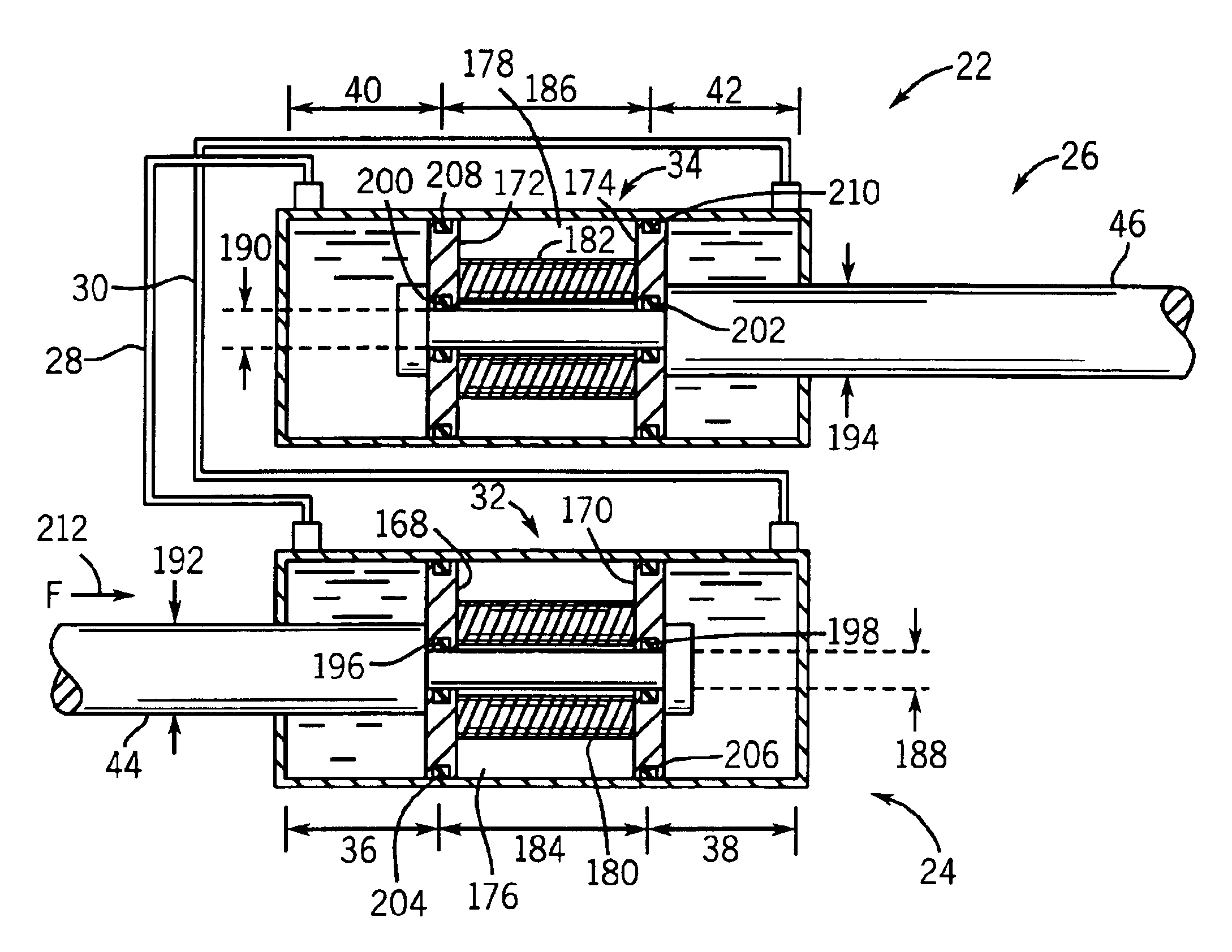
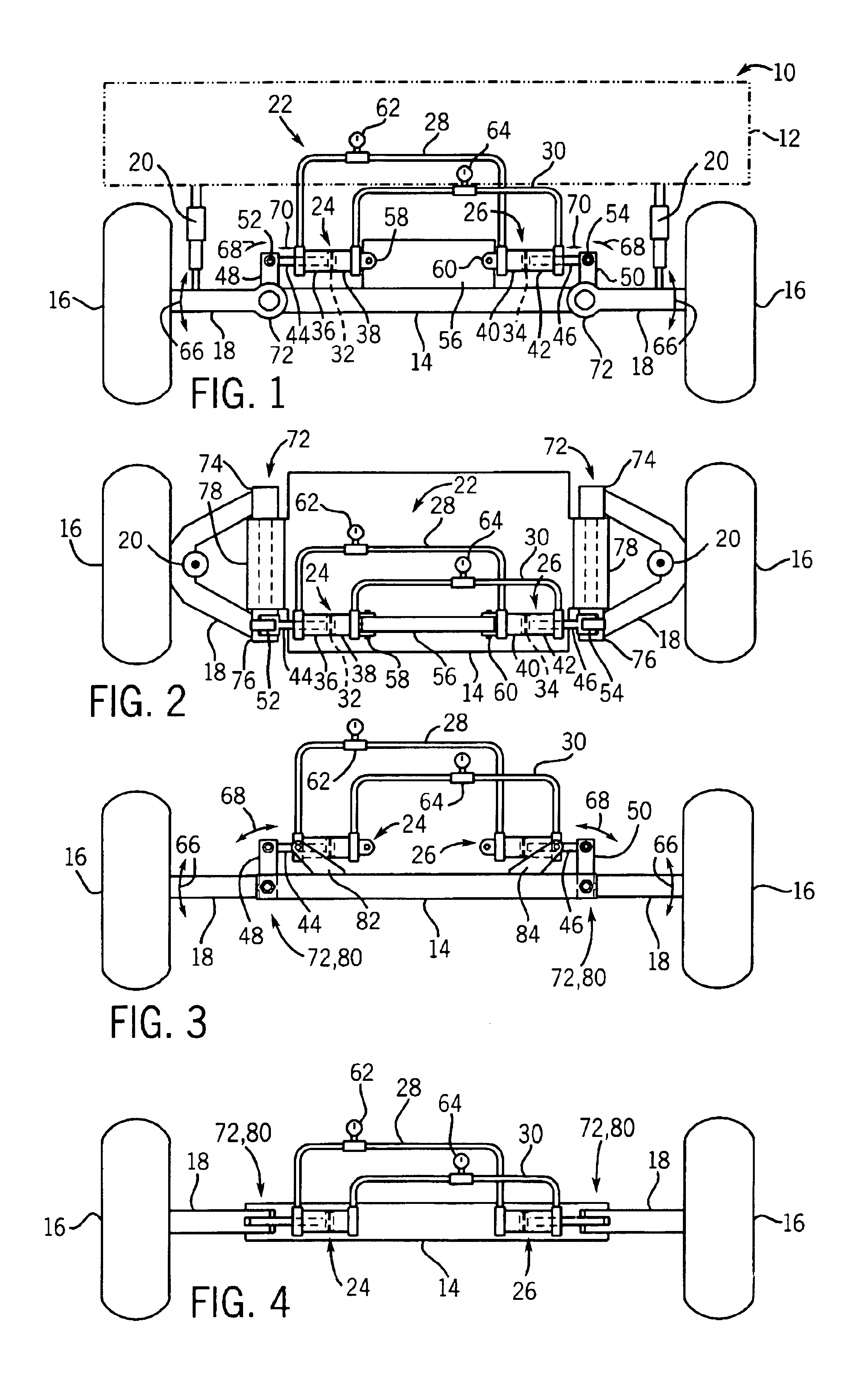
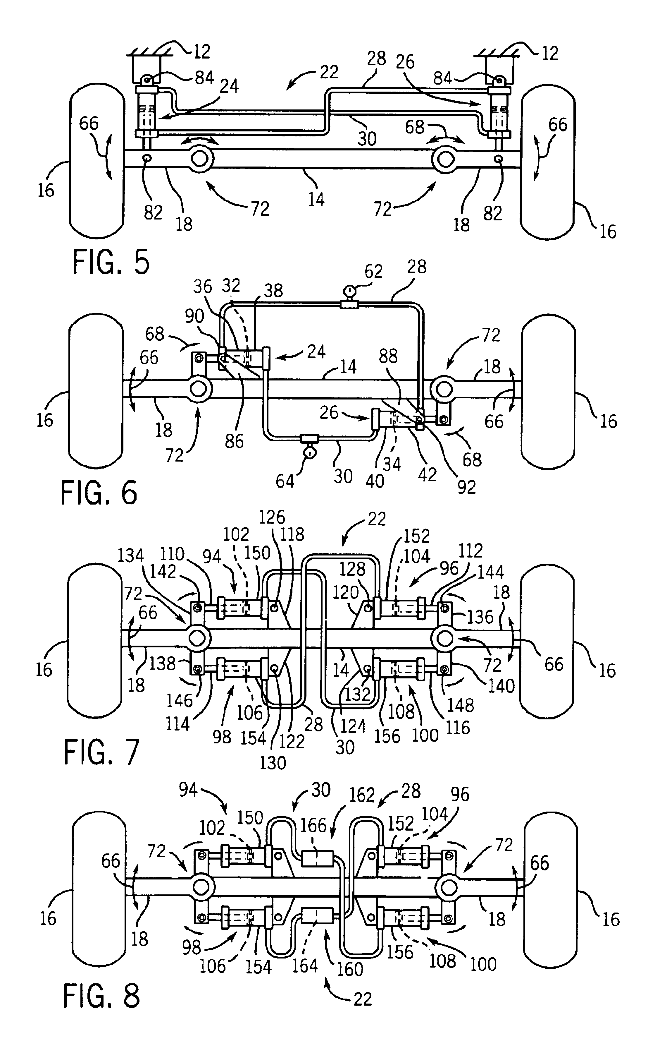
[0018]Turning now to the drawings and referring first to FIG. 1, a vehicle is illustrated in accordance with the present technique and designated generally by reference numeral 10. The particular vehicle 10 may embody any automotive vehicle, motorcycle, bicycle, public transportation vehicle, trailer, or any other suitable application requiring cross stabilization between movable members. In this exemplary embodiment, the vehicle 10 comprises a vehicle body 12, a frame 14, wheels 16, suspension arms 18 rotatably coupling the wheels 16 to the frame 14, spring assemblies 20 movably coupling the suspension arms 18 to the vehicle body 12, and a stabilizer assembly 22 movably coupling the suspension arms 18. The stabilizer assembly 22 comprises a plurality of stabilizer devices intercoupled by connectors. For example, the stabilizer devices may comprise piston cylinder assemblies, while the connectors comprise fluid conduits. Alternatively, the stabilizer assemblies may comprise electric...


PUM


Abstract

The present technique provides a stabilizer system comprising a plurality of piston cylinder assemblies, which have multiple interconnected chambers to provide cross compensation between suspension members coupled to those piston cylinder assemblies. The piston cylinder assemblies may have two or more chambers separated by pistons, which move in response to a load imposed on the suspension member coupled to that piston cylinder assembly. As the piston moves in response to movement of the corresponding suspension member, a fluid pressure is transmitted to another suspension member to distribute the load between the two suspension members.

Description

BACKGROUND OF THE INVENTION[0001]The present invention relates generally to the field of linkage control systems, and more particularly to stabilizers for vehicle suspension systems. In the present invention, hydraulic assemblies are coupled to a plurality of movable suspension members to control movement between the movable suspension members.[0002]All vehicles generally have some sort of suspension system to control movement of the vehicle during maneuvering, traveling through various terrains, loading the vehicle, and various other situations. Most vehicles have a combination of linkages, shock absorbers (e.g., air, gas, hydraulic, mechanical or spring, etc.), and stabilizer members arranged in a standard suspension architeture. In general, the linkages facilitate movement of the wheels relative to the vehicle, the shock absorbers provide cushioning between the linkages and the vehicle, while the stabilizer members are provided to distribute a load between the various linkages fo...

Claims


Application Information

Patent Timeline
IPC IPC(8): B60G21/073B60G21/00
CPCB60G21/073B60G2202/41B60G2204/13B60G2204/8304B60G2204/8306B60G2300/02B60G2400/61B60G2400/63
Inventor TROTTER, JASON K.DUTZI, ROBERT K.KING, THOMAS S.
Owner ILLINOIS TOOL WORKS INC
Features
  • Generate Ideas
  • Intellectual Property
  • Life Sciences
  • Materials
  • Tech Scout
  • Unparalleled Data Quality
  • Higher Quality Content
  • 60% Fewer Hallucinations
Learn More