Drainage catheter with bifurcating tip

a technology of draining catheter and bifurcating tip, which is applied in the field of draining catheter with bifurcating tip, can solve the problems of injuring patients with filled balloons, many patients experiencing discomfort when catheterized,

Inactive Publication Date: 2005-08-16
CIVCO MEDICAL INSTR CO
View PDF36 Cites 43 Cited by
  • Summary
  • Abstract
  • Description
  • Claims
  • Application Information

AI Technical Summary

Benefits of technology

[0028]Still another embodiment of the invention relates to a urethral catheter, comprising an elongate body having a distal end and a proximal end and at least one lumen therethrough; at least a first retention member, the at least first retention member being generally associated with the distal end of the elongate body and selectively disposed in at least an insertion state and a retention state, wherein, in the insertion state, the at least first retention member is generally aligned with the elongate body and insertable along a urethra of a mammal; and, in the retention state, at least a portion of the at least first retention member is radially spaced apart from the elongate body, wherein, upon the application of a force of less than about 10 Newtons directed generally proximally along the elongate body, the at least one retention member resists proximal movement of the catheter along the urethra and, upon the application of a force of less than about 25 Newtons directed generally proximally along the elongate body, the at least one retention member returns to an insertion state to permit withdrawal of the catheter along the urethra.
[0029]Upon the application of a force of less than about 20 Newtons directed generally proximally along the elongate body, the at least one retention member may return to an insertion state to permit withdrawal of the catheter along the urethra.
[0030]Upon the application of a force of less than about 15 Newtons directed generally proximally along the elongate body, the at least one retention member may return to an insertion state to permit withdrawal of the catheter along the urethra.

Problems solved by technology

Because the balloon must be bulky in order to retain the catheter tip, many patients experience discomfort when catheterized particularly if the balloon contacts the trigone, which is very sensitive.
Moreover, the filled balloon may injure the patient if traumatically withdrawn from the bladder.

Method used


Image

  • Drainage catheter with bifurcating tip
  • Drainage catheter with bifurcating tip
  • Drainage catheter with bifurcating tip

Examples


Embodiment Construction

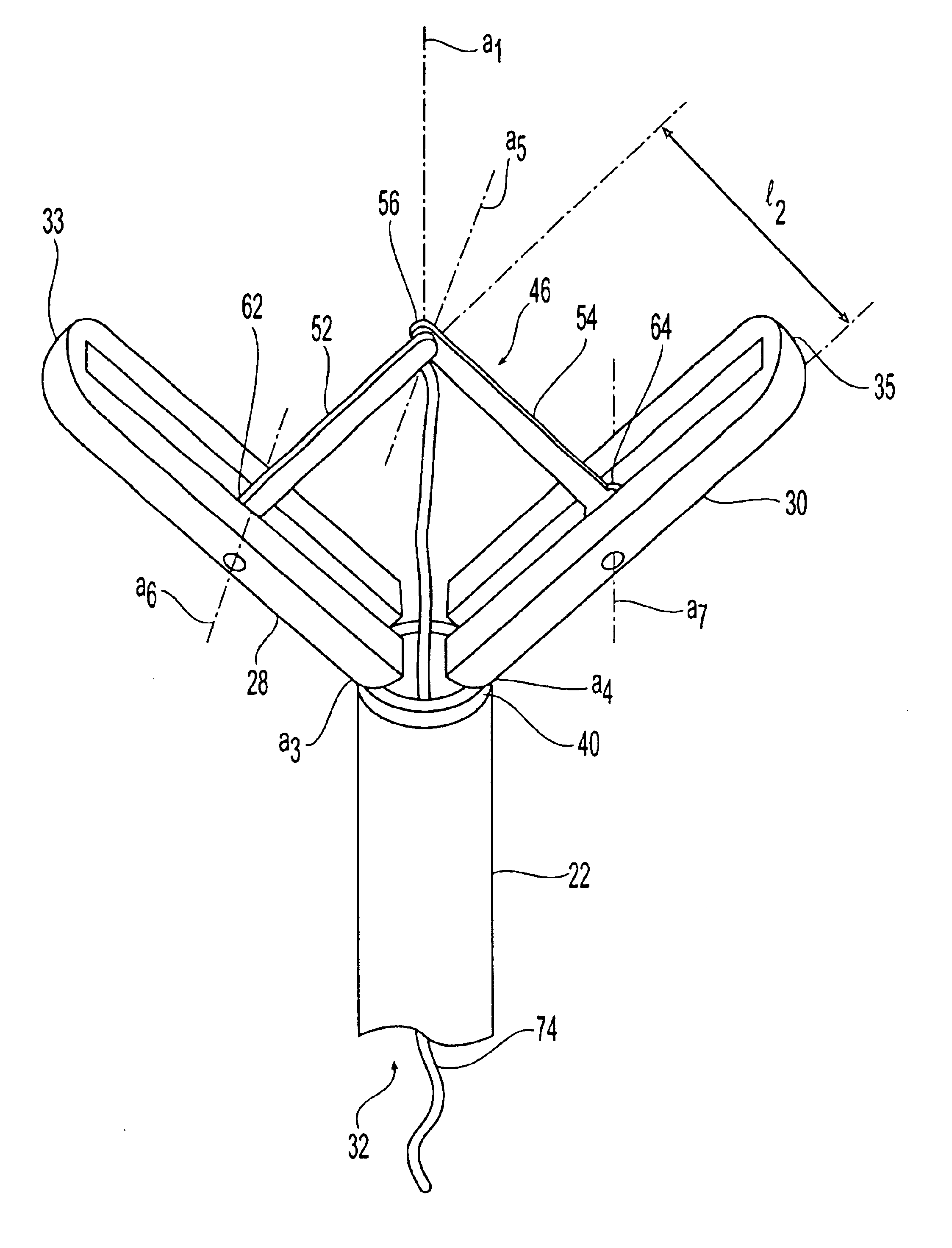
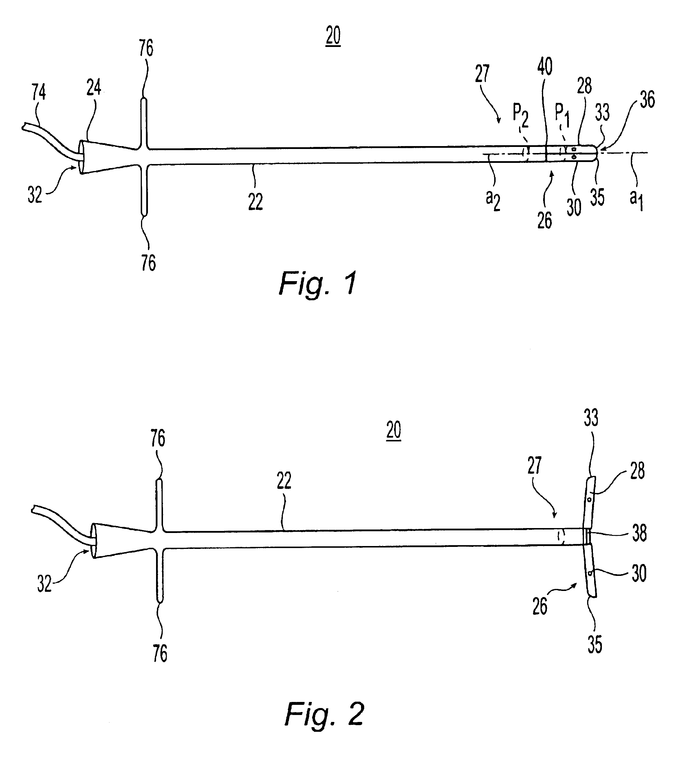
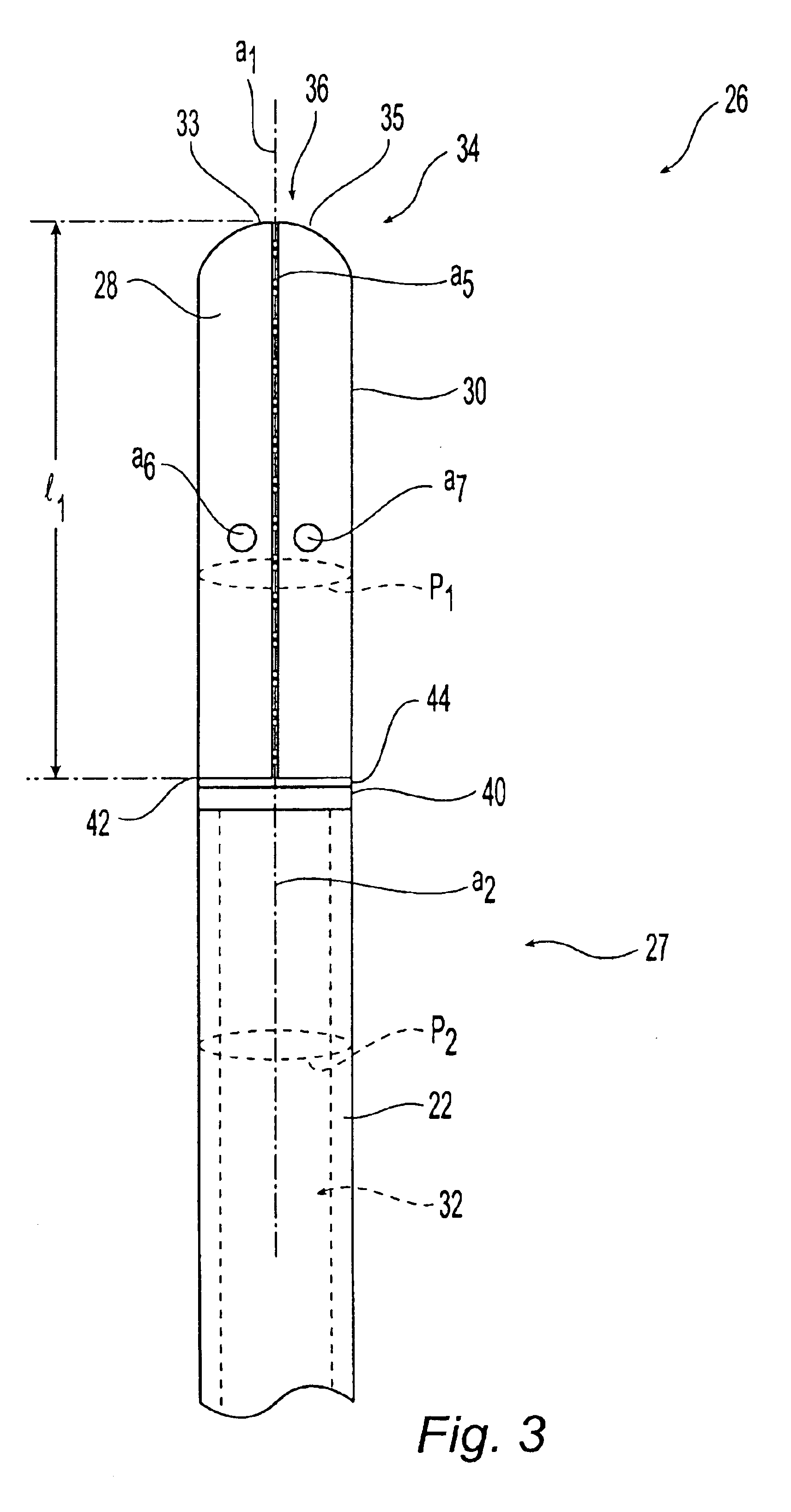
[0057]Referring to FIGS. 1 and 2, a catheter 20 of the present invention is shown including an elongate body 22. Catheter 20 has a proximal portion 24 and a distal portion 26. The catheter 20 may be configured in at least either an insertion state or a retention state, as shown in FIGS. 1 and 2, respectively. In the insertion state, catheter 20 is insertable along a passageway or lumen of a mammal until at least a portion of distal portion 26 resides within a cavity of the mammal. In the insertion state, catheter 20 may be removed along the passageway or lumen of a mammal without causing injury thereto. Distal portion 26 preferably includes at least two retention members 28, 30 which are movably associated with catheter 20. In the retention state shown in FIG. 2, at least a portion of at least one of retention members 28, 30 is radially extended, thereby resisting proximal movement of catheter 20 along the passage. In a preferred embodiment, both retention members 28, 30 are radiall...


PUM


Abstract

The present invention relates to a catheter that includes an elongate body having distal and proximal ends, the elongate body having at least one lumen therethrough, a distal portion of the elongate body having a perimeter. First and second retention members of the catheter are first and second retention members selectively disposed in either an insertion state or a retention state. In the insertion state, the first and second retention members form a distal body defining a central axis, the central axis being generally spaced apart from the perimeter of the distal portion of the elongate body, the distal body and elongate body insertable along a passageway of a mammal. In the retention state, the first and second retention members are selectively disposed in a spaced apart configuration to resist proximal movement of the catheter along the passage of the mammal.

Description

FIELD OF THE INVENTION[0001]The present invention relates to catheters and to retention devices for removably retaining catheters within a body.BACKGROUND OF THE INVENTION[0002]Urinary catheters may be used to drain urine from the bladder of a catheterized individual. One known catheter, the Foley catheter, includes a balloon located near the tip of a tube sized to pass through the urethra. Once the tip is within the bladder, the balloon is filled with fluid to retain the tip in the bladder. Because the balloon must be bulky in order to retain the catheter tip, many patients experience discomfort when catheterized particularly if the balloon contacts the trigone, which is very sensitive. Moreover, the filled balloon may injure the patient if traumatically withdrawn from the bladder.[0003]There is a need for a catheter that may be disposed within a bladder and retained without retention by a bulky fluid filled balloon. Additionally, there is a need for a catheter that may be inserted...

Claims


Application Information

Patent Timeline
Patent Type & Authority Patents(United States)
IPC IPC(8): A61M25/02A61M25/04A61M25/00
CPCA61M25/0017A61M25/0069A61M25/04A61M27/008A61M2210/1085
Inventor WHITMORE, WILLET F.BARZELL, WINSTON E.WILSON, ROGER F.
Owner CIVCO MEDICAL INSTR CO
Why Eureka
Try Eureka