Stick-type ignition coil having improved structure against crack or dielectric discharge
a technology of dielectric discharge and ignition coil, which is applied in the direction of transformer/inductance details, inductance, electrical equipment, etc., can solve the problems of affecting the production of required high voltage, and affecting the operation of the ignition coil. , to achieve the effect of reducing distortion, reducing dielectric breakdown, and restricting the voltage to be applied to the ignition plug
- Summary
- Abstract
- Description
- Claims
- Application Information
AI Technical Summary
Benefits of technology
Problems solved by technology
Method used
Image

Examples
first embodiment
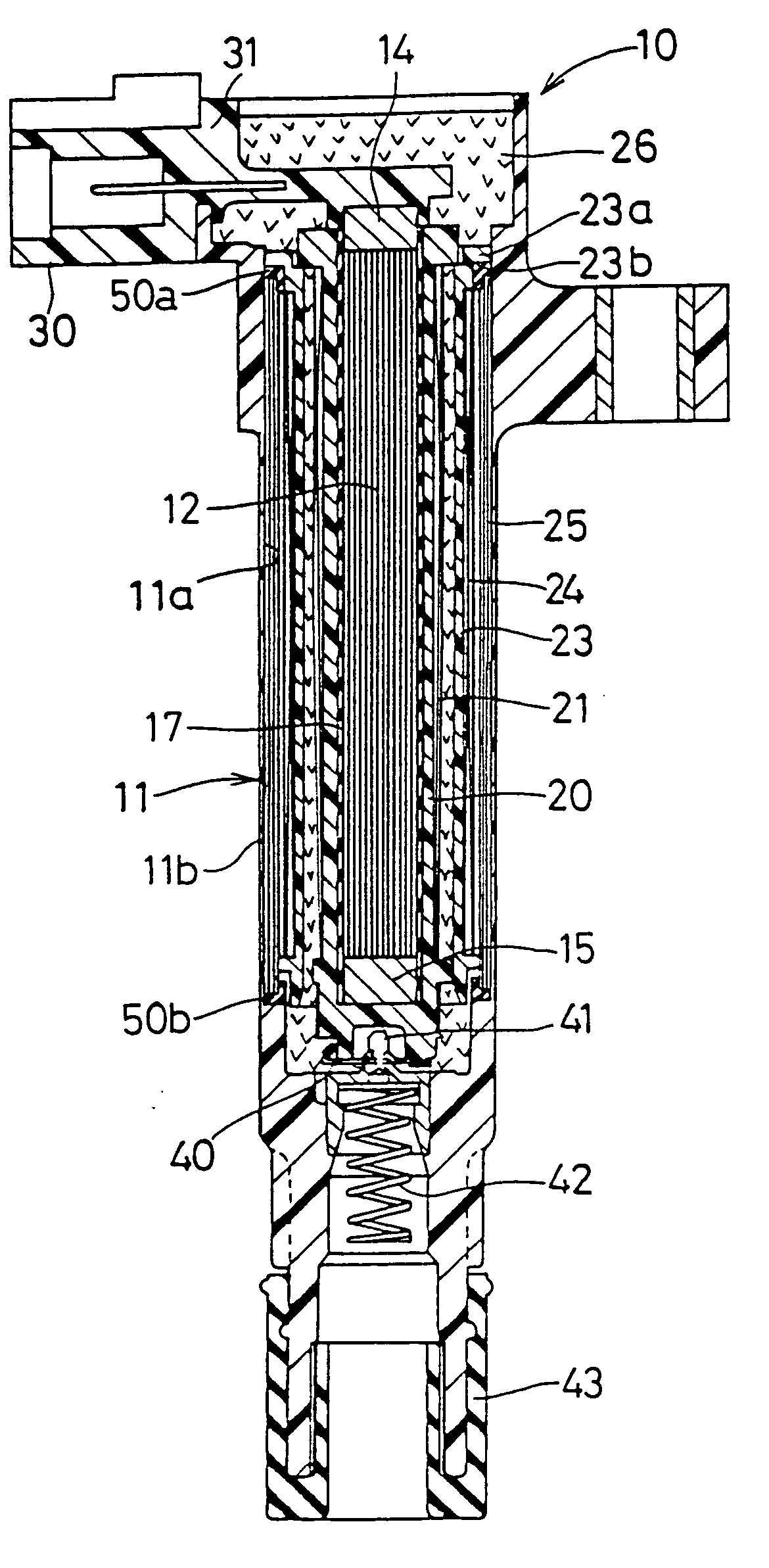
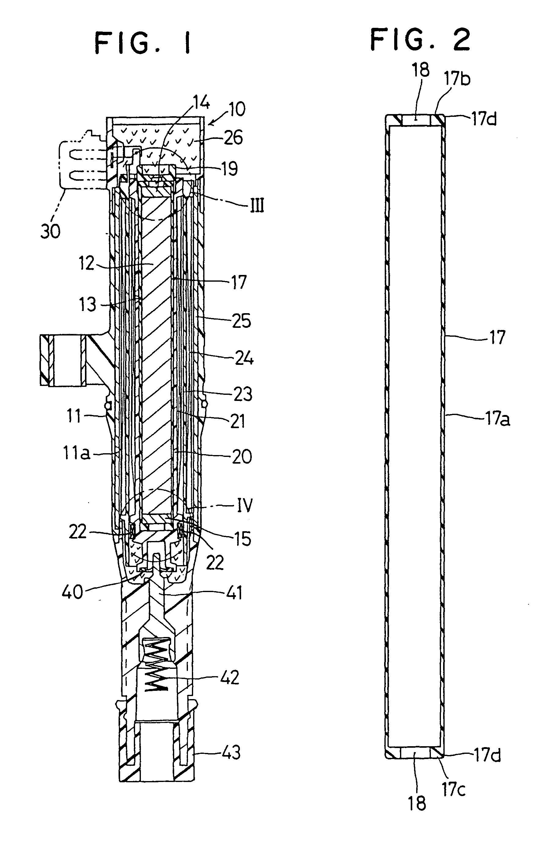
[0061]An ignition coil 10 is fitted, as shown in FIG. 1, in a plug hole (not shown) which is formed in each cylinder head of an internal combustion engine, and is electrically connectable to a spark ignition plug.
[0062]The ignition coil 10 has a cylindrical housing 11 made of a resin, in which an accommodating chamber 11a is formed to accommodate a central core assembly 13, a secondary spool 20, a secondary coil 21, a primary spool 23, a primary coil 24 and an outer core 25. The central core assembly 13 is comprised of a core 12, and permanent magnets 14 and 15 arranged at the two longitudinal ends (top and bottom) of the core 12. An epoxy resin 26 filled in the accommodating chamber 11a infiltrates between the individual members of the ignition coil 10 to ensure the electric insulations among the members as a resin insulating material.
[0063]The core 12 having a column shape is provided by laminating a thin silicon (Si) steel sheet radially to have a generally circular transverse se...
second embodiment
[0073]In the second embodiment shown in FIG. 5, no the permanent magnets are arranged at the two longitudinal ends of the core 12, but the core 12 itself provides the central core assembly 13. The core 12 is covered partially at the outer circumference, at the two end corners and at the two longitudinal end faces with the cylindrical member 17.
[0074]In the second embodiment, too, the cracks can be prevented around the outer circumference of the core 12 and especially at the secondary spool 20 and the epoxy resin 26 in the vicinity of the two end corners of the core 12, where the cracks might otherwise be liable to occur, so that the electric discharge between the high voltage side and the central core assembly 13 can be prevented. As a result, the desired high voltage can be applied to the ignition plug.
[0075]As a result of the elastic deformation of the cylindrical member 17, moreover, the forces for the core 12 to receive in the radial direction and in the longitudinal direction a...
third embodiment
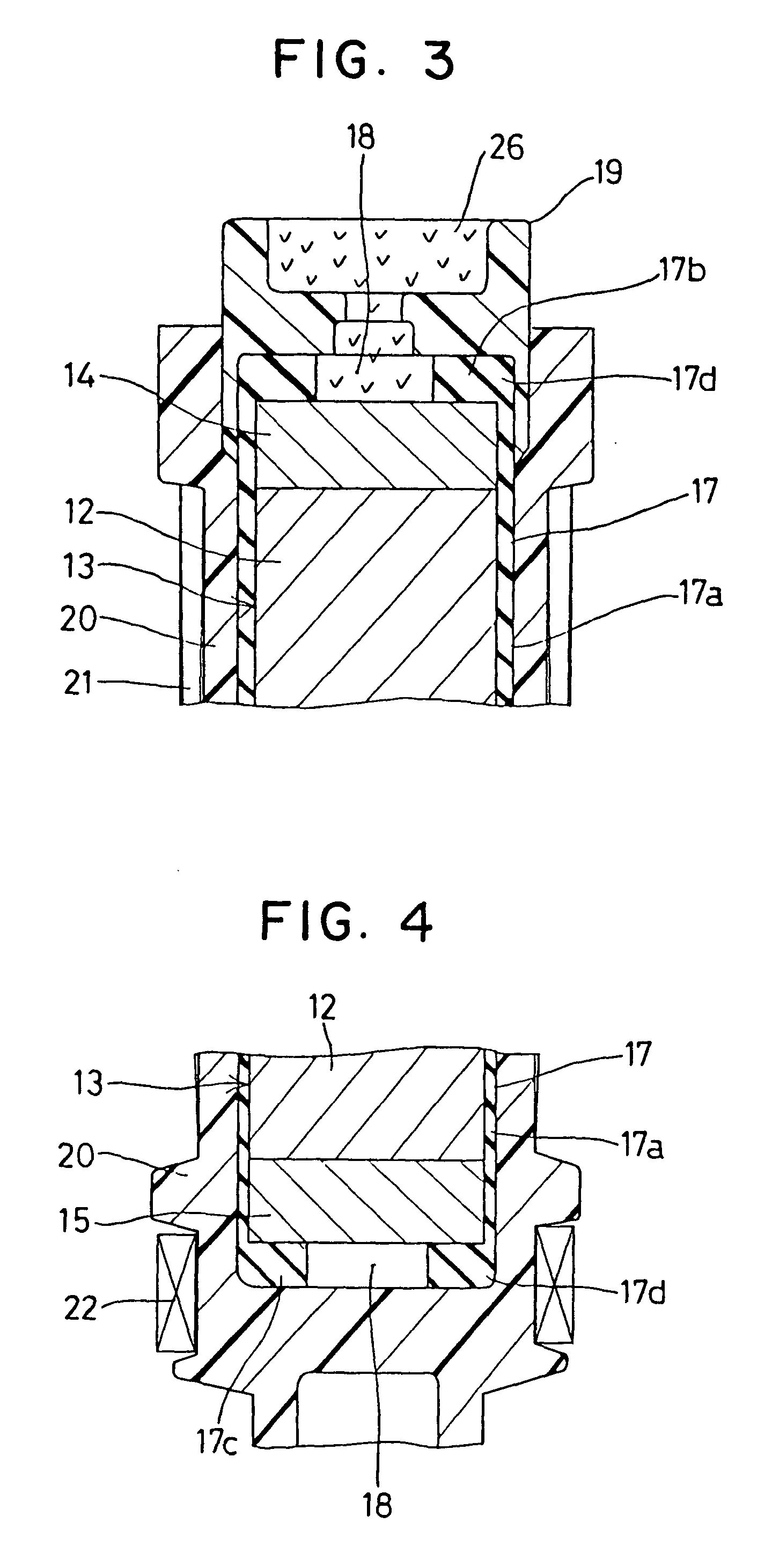
[0076]In the third embodiment shown in FIGS. 6 and 7, the cylindrical member 17 made of rubber to act as the first buffer member is comprised of the cylindrical part 17a, an angled part 17b and a bottom disc part 17c acting as a second buffer member, and is shaped into a bottomed cylindrical shape, as closed at the bottom longitudinal end side of the permanent magnet 15. The cylindrical part 17a covers the outer circumference of the central core assembly 13, the annular angled part 17b covers the end corner of the permanent magnet 15, and the disc part 17c covers the bottom end face of the permanent magnet 15. The cylindrical member 17 is extended upwardly at the side of the permanent magnet 14 over the end face of the permanent magnet 14. A plate member 17e made of rubber to act as the first buffer member and the second buffer member is formed into a disc shape separate from the cylindrical member 17 and has a larger diameter than the permanent magnet 14. The end corner of the perm...
PUM
| Property | Measurement | Unit |
|---|---|---|
| weight % | aaaaa | aaaaa |
| elastic modulus | aaaaa | aaaaa |
| elastic modulus | aaaaa | aaaaa |
Abstract
Description
Claims
Application Information
 - R&D
- Intellectual Property
- Life Sciences
- Materials
- Tech Scout
- Unparalleled Data Quality
- Higher Quality Content
- 60% Fewer Hallucinations
Browse by: Latest US Patents, China's latest patents, Technical Efficacy Thesaurus, Application Domain, Technology Topic, Popular Technical Reports.
© 2025 PatSnap. All rights reserved.Legal|Privacy policy|Modern Slavery Act Transparency Statement|Sitemap|About US| Contact US: help@patsnap.com