Drive device for stamping strip, unwinding module and stamping machine provided therewith

a technology of a drive device and a stamping machine, which is applied in the directions of printing, web handling, transportation and packaging, etc., can solve the problems of reducing the time taken, reducing the active position of several devices on one wide reel, and reducing the efficiency of the operator, so as to reduce the time taken

Active Publication Date: 2015-03-19
BOBST MEX SA
View PDF9 Cites 1 Cited by
  • Summary
  • Abstract
  • Description
  • Claims
  • Application Information

AI Technical Summary

Benefits of technology

[0012]A principal aim of the present invention is to refine a drive device for unwinding a reel of foil in an unwinding module in a stamping machine. A second aim is to make a drive device simpler and to reduce the time taken to put it into an active position. A third aim is to resolve the technical problems mentioned for the prior art document. A fourth aim is to provide an unwinding module incorporating one or more drive devices for one or more reels. A fifth aim is to incorporate a device in a stamping machine. Yet another aim is that of realizing a stamping machine with an unwinding module.
[0020]The biasing means maintain the belt at a constant tension when following the unwinding of the reel, thus suppressing the shortcoming in the operating area. Furthermore, the tension of the belt can be adapted as a function of the necessary power, the quality of the hub and the quality of the unwinding of the foil.
[0022]The disengageable and actuatable means only ensure the belt is tensioned once the device has been put into the active position. By way of the disengageable and actuatable means, the belt is tensioned at the last moment of being put into the active position. A slack or weakly tensioned belt during take-up of the active position neither makes the reel turn to no purpose, nor does it make it block the reel. Taking up the position becomes much more ergonomic.

Problems solved by technology

This phenomenon leads to reject of stamping foil.
A second disadvantage observed is the difficulty of putting several devices into the active position on one wide reel.
The operator thus has to press very strongly and with a great deal of effort to put the second device on the reel.
The forcing makes it difficult to place this second device in position and the foil is very greatly crumpled on the surface of the reel.
Yet another disadvantage is a shortcoming in the operating area.

Method used


Image

  • Drive device for stamping strip, unwinding module and stamping machine provided therewith
  • Drive device for stamping strip, unwinding module and stamping machine provided therewith
  • Drive device for stamping strip, unwinding module and stamping machine provided therewith

Examples


Embodiment Construction

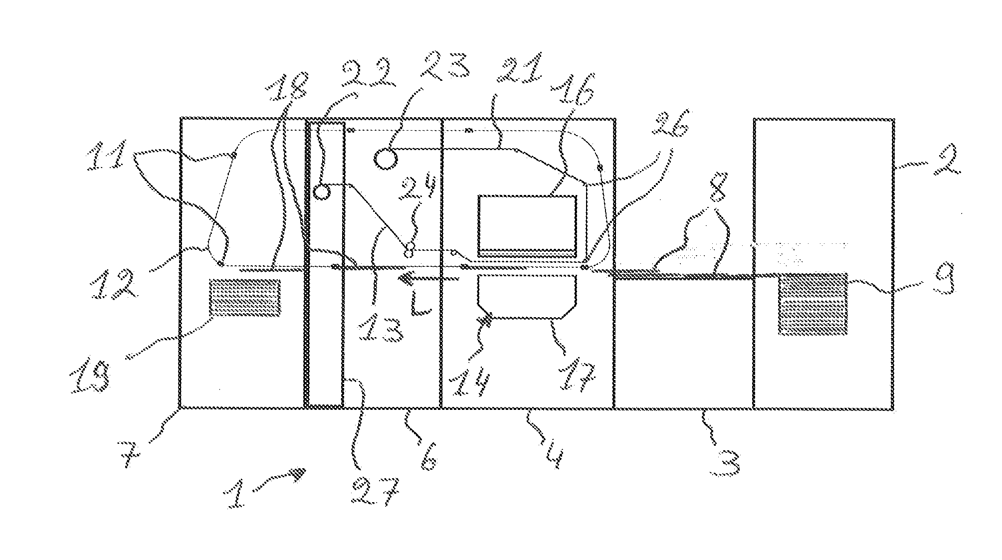
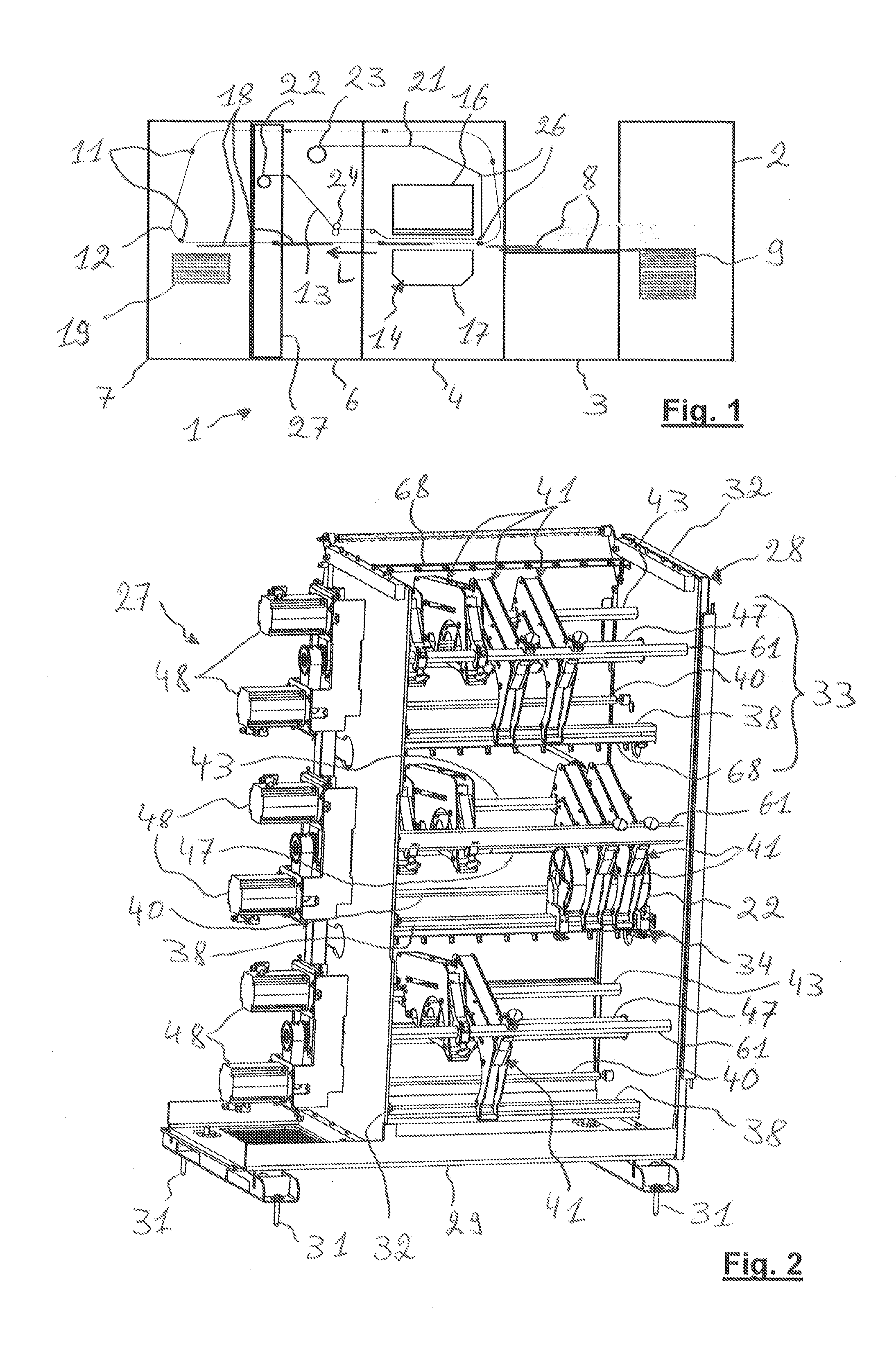
[0035]As illustrated in FIG. 1, a hot foil stamping machine, in the present case a gilding machine 1, comprises, in sequence, different stations 2, 3, 4, 6 and 7 which are placed side by side and are interdependent. From upstream to downstream the machine 1 comprises an infeed station 2, a feed table 3, a stamping station 4, a station for supplying and recovering foil 6 and a delivery station 7.

[0036]The sheet elements, in the present case cardboard sheets 8, having to be covered with gilded patterns, are placed into the machine 1 in the infeed station 2 in the form of a stack 9. The sheets 8 are removed one by one from the top of the stack 9 and are placed in shingle stream on the feed table 3. At the end of the shingle stream, the front sheet is positioned precisely. Each sheet is then gripped and conveyed individually from the output of the feed table 3 through the machine 1 as far as up to the delivery station 7 by a conveyor.

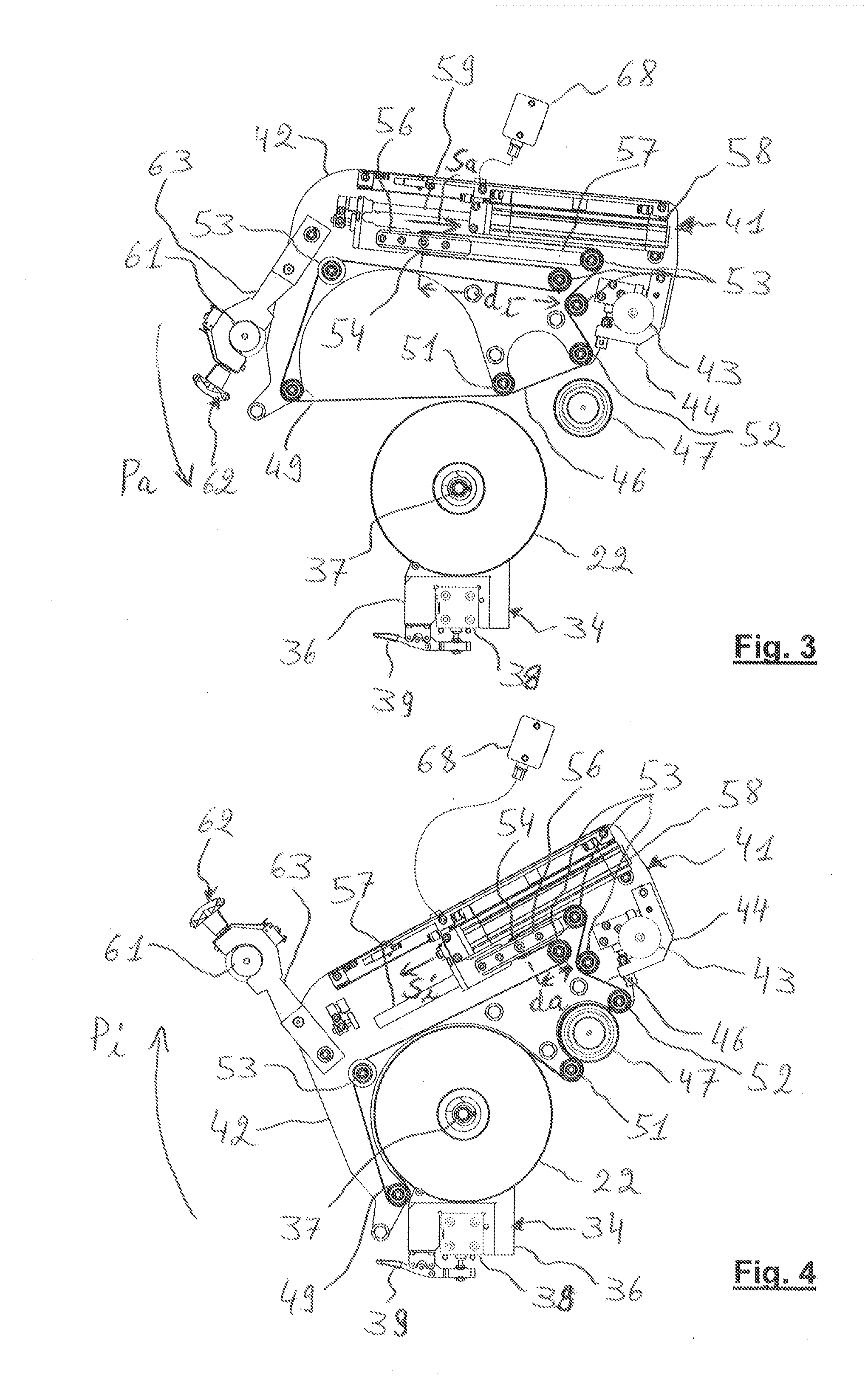
[0037]The conveyor is generally constituted by a grip...


PUM

PropertyMeasurementUnit
widthaaaaaaaaaa
widthaaaaaaaaaa
widthaaaaaaaaaa

Abstract

Drive device for unwinding a reel of foil in an unwinding module of a stamping machine, having an inactive position, and an active position in engagement with the reel, and comprising: a belt, having an inactive configuration, and an active configuration for contacting a portion of the reel and driven by a driver of the module so as to unwind the reel, rollers, maintaining the belt in the inactive and the active configuration, a translatable roller, which engages the belt and compensates for variations in length when the belt moves from the inactive to the active configuration, and a biasing arrangement, attached to the roller and thereby keeping the belt tensioned in both the inactive and the active configuration, and the biasing arrangement is actuated and disengaged from the belt, to move the belt from the inactive to the active configuration and vice versa.

Description

[0001]The present invention relates to a drive device for rotatively driving a reel of stamping foil. The invention refers to an unwinding module for stamping foil, equipped with at least one such drive device. The invention relates to a stamping machine for the manufacture of packaging comprising at least one such drive device. The invention also relates to a stamping machine for the manufacture of packaging provided with an unwinding module equipped with at least one such drive device.[0002]In the area of the manufacture of packaging, for example that destined for the luxury industry, a converting machine by stamping applies patterns onto a sheet element by means of pressure. The patterns, for example usually metallized texts and / or decorations, are obtained by means of a shape to be stamped or a plate. The patterns originate from portions of a film derived from one or more stamping foils.[0003]In the stamping machine, the sheet elements are taken off a stack located upstream, gri...

Claims


Application Information

Patent Timeline
Patent Type & Authority Applications(United States)
IPC IPC(8): B41F19/02B65H20/06B65H16/10
CPCB41F19/02B65H16/106B65H2301/5126B65H2301/44322B65H20/06B41F19/068B65H18/145B65H2301/4493B65H2403/25B65H2801/81B26F1/40
Inventor SUN, XIGUANG
Owner BOBST MEX SA
Why Eureka
Try Eureka