Position detection system and receiver

Active Publication Date: 2019-04-25
MURATA MFG CO LTD
View PDF0 Cites 2 Cited by
  • Summary
  • Abstract
  • Description
  • Claims
  • Application Information

AI Technical Summary

Benefits of technology

[0017]The moving object may send the beacon periodically, and the control unit may determine the waiting time corresponding to the signal strength such that a maximum value of the waiting time is smaller than a period of the beacon sent from the moving object.
[0018]With those features, since the maximum value of the waiting time is smaller than the beacon sending period, the receiver i

Problems solved by technology

Accordingly, when the transmission paths are constituted by communication cables, the communication cables are required in number corresponding to the number of receivers, and laying the communication cables is complicated.
When the transmission paths are constituted using radio, the moving space is limited to a

Method used


Image

  • Position detection system and receiver
  • Position detection system and receiver
  • Position detection system and receiver

Examples


modification 1

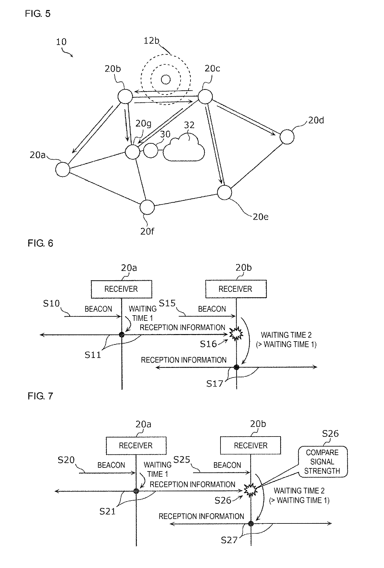
[0074]In Modification 1, when the receiving unit 22 in each of the receivers 20a to 20g receives the beacon, the control unit 24 sends the first reception information after the lapse of a waiting time that is set to be longer as the received beacon has lower signal strength. However, the control unit 24 stops sending of the first reception information when the second reception information is received from the other receiver during the lapse of the waiting time after receiving the beacon.

[0075]FIG. 6 is a communication sequence chart illustrating the operations of the receivers in Modification 1. FIG. 6 illustrates the operations in the case of receiving the same beacon by two receivers 20a and 20b. It is assumed that the signal strength of the beacon received by the receiver 20a is higher than the signal strength of the beacon received by the receiver 20b.

[0076]In the receiver 20a, when the receiving unit 22 receives the beacon (S10), the control unit 24 determines, from the signal...

modification 2

[0081]In Modification 2, on the premise of sending the first reception information during the waiting time as in above Modification 1, when the receiving unit 22 in each of the receivers 20a to 20g receives the beacon during the waiting time, the control unit 24 further compares the signal strength of the received beacon (signal strength of the beacon received by the relevant receiver being also called “first signal strength” hereinafter) with the signal strength indicated by information contained in the second reception information (the signal strength indicated by the information contained in the second reception information being also called “second signal strength” hereinafter), and stops sending of the first reception information if the second signal strength is higher than the first signal strength. A margin (offset) may be taken into consideration in the above comparison. For instance, the sending of the first reception information may be stopped if the second signal strength...

modification 3

[0087]In Modification 3, each of the moving objects 12a to 12c sends the beacon containing a sequence number that is updated whenever it sends the beacon.

[0088]The control unit 24 in each of the receivers 20a to 20g operates basically in the same manner as that in above Modification 2. When sending the first reception information, however, the control unit 24 sends, from the sending unit 23, the first reception information to which the sequence number is added. Furthermore, when comparing the first signal strength and the second signal strength in above Modification 2, the control unit 24 compares the signal strengths of the beacons having the same sequence number.

[0089]FIG. 8 is a communication sequence chart illustrating the operations of the receivers according to Modification 3. It is here assumed that there exist the same situations as those in Modification 1 illustrated in FIG. 6 (namely, that two receivers 20a and 20b receive the same beacon, and that the signal strength of t...


PUM


Abstract

A position detection system (10) includes receivers (20a to 20g) constituting a radio mesh network, and a gateway device (30). Each of the receivers (20a to 20g) includes a receiving unit (22), a sending unit (23), and a control unit (24). When the receiving unit (22) in each of the receivers (20a to 20f) receives the beacon, the control unit (24) generates first reception information containing information indicating signal strength of the received beacon and identification information of the relevant receiver, and sends the first reception information from the sending unit (23). When the receiving unit (22) receives second reception information, the control unit (24) sends the second reception information. When receiving the second reception information generated by the other receiver, the receiver (20g) connected to the gateway device (30) sends the received second reception information to the server device (34) through the gateway device (30).

Description

[0001]This is a continuation of International Application No. PCT / JP2017 / 022934 filed on Jun. 21, 2017 which claims priority from Japanese Patent Application No. 2016-132790 filed on Jul. 4, 2016. The contents of these applications are incorporated herein by reference in their entireties.BACKGROUND OF THE DISCLOSUREField of the Disclosure[0002]The present disclosure relates to a position detection system for detecting a position of a moving object, and to a receiver constituting the position detection system.Description of the Related Art[0003]Hitherto, various techniques have been proposed as position detection systems for detecting the positions of moving objects (see, for example, Patent Document 1).[0004]Patent Document 1 discloses a position detection system utilizing RFID (Radio Frequency IDentification) in which an RF tag sending a beacon repeatedly is attached to a moving object and receivers are arranged at a plurality of positions (known positions) in a moving space. When ...

Claims


Application Information

Patent Timeline
IPC IPC(8): G01S5/02G01S11/06G01C21/20H04W64/00
CPCG01S5/0221G01S11/06G01C21/206H04W64/00H04W88/16H04W4/02H04W84/00H04W4/029G01S5/02213H04W84/22G01S5/02216G01S2205/02
Inventor NISHIMURA, TETSU
Owner MURATA MFG CO LTD
Why Eureka
Try Eureka