Heat pump system with multi-stage compression

Inactive Publication Date: 2006-11-30
PURDUE RES FOUND INC
View PDF17 Cites 56 Cited by
  • Summary
  • Abstract
  • Description
  • Claims
  • Application Information

AI Technical Summary

Benefits of technology

[0012] According to this aspect of the invention, the heat pump system provides increased flexibility while allowing for the use of relatively lowcost fixed-speed compressors. Alternatively, one of the compressors may be a variable capacity compressor with a high and low setting to provide additional flexibility in the capacity of the system. An economizer may also be used to provide still further flexibility and increased total output for the system. According to a preferred aspect of the invention, one or both of the compressors of the heat pump system can be selectively caused to operate based on a ratio of the evaporating and condensing pressures of the refrigerant within the heat pump system, as opposed to sensing temperatures to control the system. With this approach, only one of the compressors is operated if the ratio is less than a predetermined value for the ratio, and both compressors are operated if the ratio is greater than the predetermined value. As such, if the pressure ratio were to rise to a level at which the compressors could be damaged if operated individually, the other compressor is started to provide a two-stage operating mode.
[0013] According to another aspect of the invention, a heat pump system is provided having a compressor section with at least two compressors, first and second heat exchangers selectively fluidically connected to the compressor section to enable flow of a refrigerant between the compressor section and the first heat exchanger, between the first and second heat exchangers, and between the compressor section and the second heat exchang

Problems solved by technology

However, in colder northern climates, the use of heat pumps presents additional challenges.
One issue is that the performance of heat pump systems decreases in colder temperatures when heating capacity is most needed.
Although heat pump systems that contain a single compressor may be designed to operate at very low ambient temperatures, such systems show decreased performance at higher temperatures.
Also, the heating capacity of a single-compressor system will greatly exceed the cooling capacity of the system, providing an inefficient and wasteful heating-to-cooling capacity ratio.
A system with excess heating capacity will also have to cycle on and off more frequently at higher ambient temperatures in order to reduce its capacity, leading to a reduced life span and decreased system efficiency.
These solutions, however, increase the price of the system and eliminate the biggest advantage of the heat pump, namely, its low installation cost.
The supplemental heating system, however, reduces the desirability of a heat pump in the first place, and leads to significantly increased energy costs during the coldest months of the year.
Al

Method used


Image

  • Heat pump system with multi-stage compression
  • Heat pump system with multi-stage compression
  • Heat pump system with multi-stage compression

Examples


Embodiment Construction

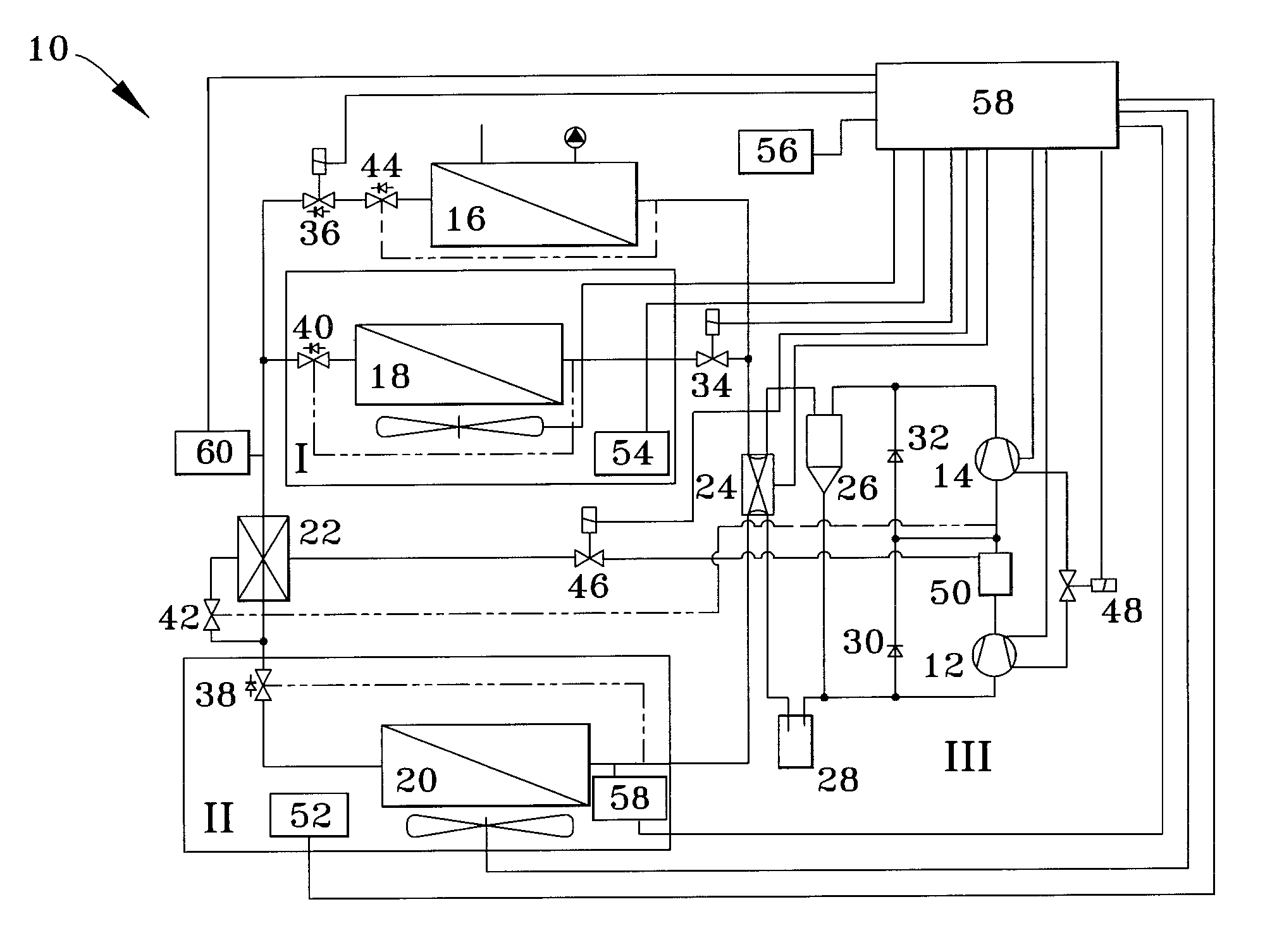
[0023] A heat pump system 10 in accordance with a preferred embodiment of the present invention is schematically represented in FIG. 1. The heat pump system 10 will be described with particular reference to residential house applications in nordic climates, it will be understood that the system 10 of this invention can find use in other applications and operating environments.

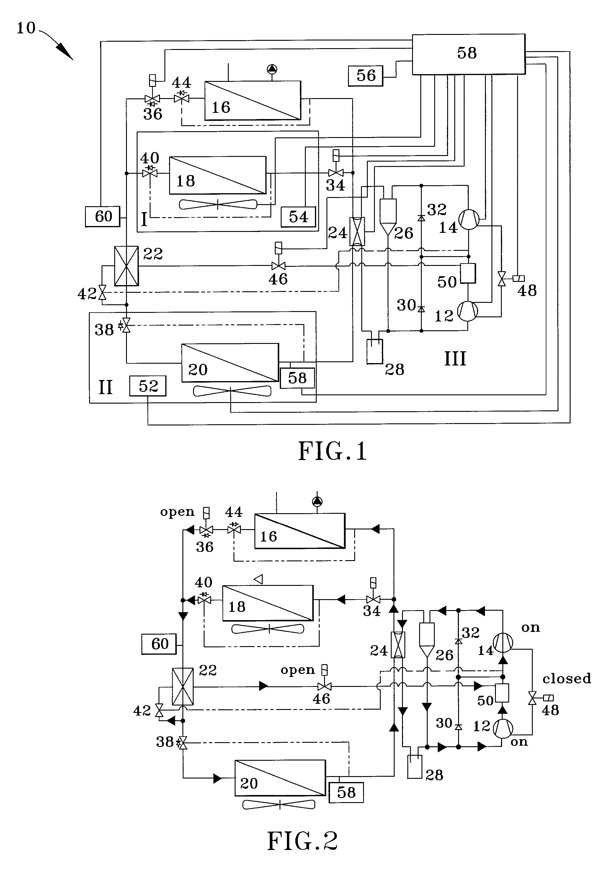
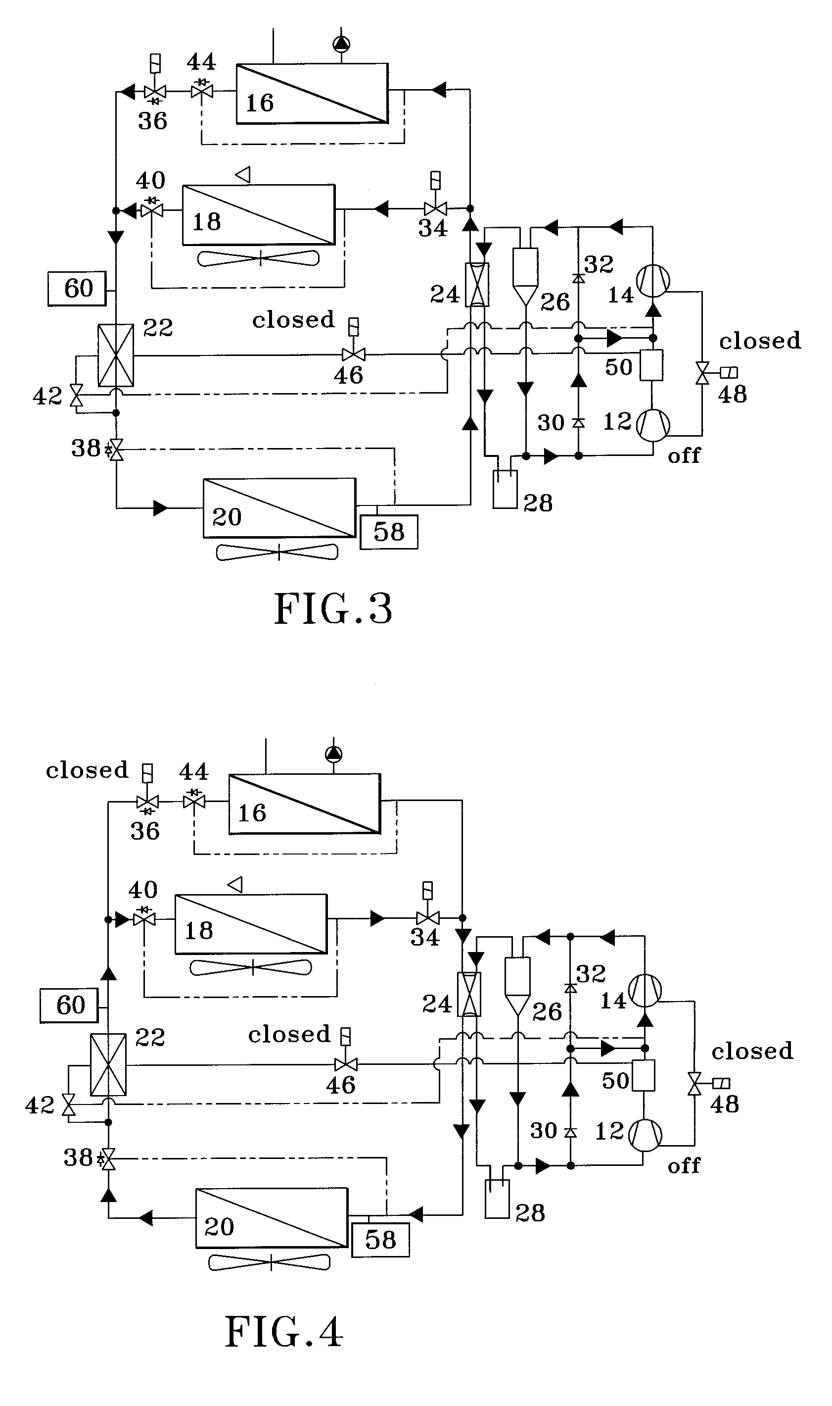
[0024] As shown in FIG. 1, the heat pump system 10 includes a low-stage compressor 12, a high stage compressor 14, an indoor refrigerant-water heat exchanger 16, an indoor refrigerant-air heat exchanger 18 for delivering heating and cooling air to the interior of the house (not shown), an outdoor refrigerant-air heat exchanger 20, a closed economizer 22, a four-way reversing valve 24, a lubricant separator 26, a suction gas accumulator 28, check valves 30 and 32 in fluidic parallel with the compressors 12 and 14, respectively, a control valve 34 for adjusting the refrigerant flow rate through the heat exchange...


PUM


Abstract

A multi-compressor heat pump system configured to provide heating and cooling over a range of ambient temperatures. The compressors can be operated independently and alone or together in series for maximum output. Heat exchangers are selectively fluidically connected to the compressors to enable refrigerant flow between the compressors and at least two heat exchangers in a manner that enables the heat pump system to be selectively operable in various modes. Preferred aspects include selectively operating the compressors based on the ratio of the evaporating and condensing pressures of the refrigerant within the heat pump system, a mixing chamber between the compressors, and a lubricant management system to prevent the accumulation of a lubricant in one of the compressors.

Description

CROSS REFERENCE TO RELATED APPLICATIONS [0001] This application claims the benefit of U.S. Provisional Application No. 60 / 685,302, filed May 27, 2005, the contents of which are incorporated herein by reference.BACKGROUND OF THE INVENTION [0002] The present invention relates generally to heating and cooling systems, and more particularly to a heating and cooling system with multiple compressors. [0003] Conventional heat pump systems utilize a reversible refrigerant flow to both heat and cool enclosed spaces, typically a building such as a house. In a heating cycle of a typical heap pump system, a compressor compresses a vaporized refrigerant to a high pressure and directs the resulting hot refrigerant vapor to an indoor heat exchanger functioning as a condenser. The indoor heat exchanger draws heat from the condensation of the refrigerant vapor to heat the house. The resulting cooled and liquid refrigerant is then directed to an expansion device and an outdoor heat exchanger where, u...

Claims


Application Information

Patent Timeline
IPC IPC(8): F25B1/10F25B13/00
CPCF25B1/10F25B13/00F25B31/004F25B2313/003F25B2313/02321Y02B30/741F25B2313/02334F25B2313/02741F25B2400/0401F25B2400/13F25B2600/0253F25B2313/02322Y02B30/70
Inventor GROLL, ECKARD A.HUTZEL, WILLIAM J.BERTSCH, STEFAN S.BOUFFARD, DAVID B.
Owner PURDUE RES FOUND INC
Why Eureka
Try Eureka