[0018]To address the problem of how best to deliver the drugs in the most cost effective manner available while producing good patient outcomes and preventing complications, the
medical device industry has essentially focused on developing methods and devices that inhibit the vascular response to the injury (
restenosis), as opposed to developing a device that causes less injury, and hence less
restenosis. One aspect of the present invention is directed to a device and method that both causes less injury to the vasculature by the use of dilatation of a
braid over a balloon causing less
dissection and more even plaque disruption at lower pressures and introduces
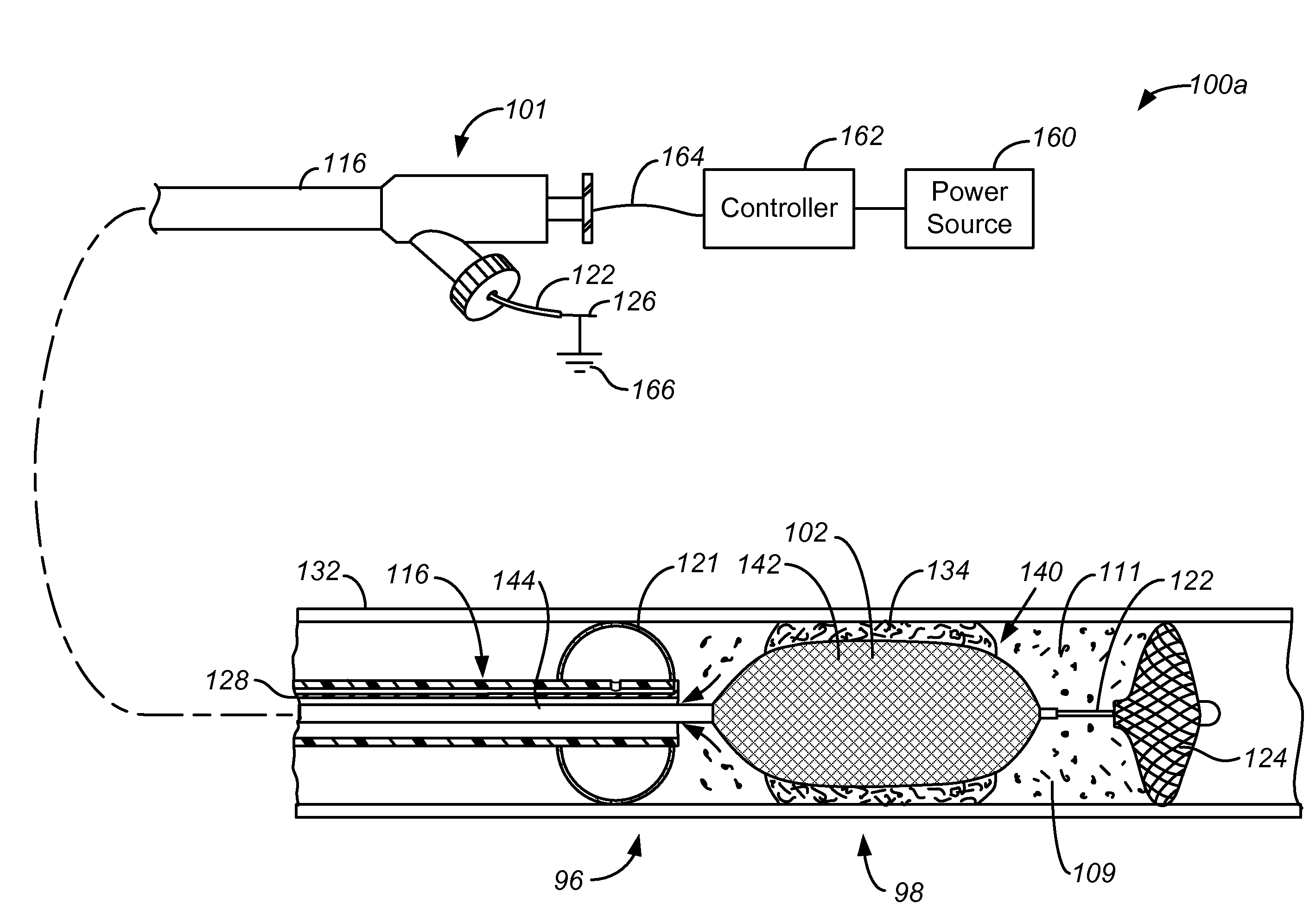
drug deep within the vessel wall; this latter act is accomplished by using proximal and distal occluders, injecting an agent, such as an anti-proliferative drug, into the region between the occluders, and performing an intervention, such as balloon
angioplasty, while the occluders and injected agent remain in place. Another aspect of the invention also helps to maintain pressure upon the vessel wall similar to prolonged
balloon inflation by using a braided, stent like structure as a temporary or transient stent. Thus less initial injury and less elastic
recoil should result in less
restenosis, and delivering a drug will further reduce or prevent the restenosis.
[0019]It is the immediate result of an intervention (the immediate
lumen diameter and the immediate residual percent
stenosis) that typically determines the late outcome after coronary or other vascular intervention. The present invention is designed to improve these two factors. An optimal outcome in
percutaneous interventions depend upon: 1) obtaining an excellent acute angiographic results with less
dissection and elastic
recoil, 2) avoiding damage to the distal vascular
bed (as with
atherectomy), and 3) reducing
smooth muscle cell proliferation with pharmacological intervention. The invention addresses all three areas.
[0023]By utilizing the balloon to expand the temporary stent, not only the pressure of the balloon is brought to bear on the obstruction, but its actions are enhanced by the overlying temporary stent structure. The wires of the temporary stent provide areas of focal force on the plaque that will allow the plaque or obstruction to be dilated with less pressure creating a controlled expansion compared to the uncontrolled rupture and dissections frequently seen with POBA. There will be a more gradual stretching and more gradual deforming of the smooth
muscle cells, and they will have an opportunity to accommodate this stretching and maintain their integrity rather than being irreparably injured as is frequently the case with POBA. Therefore the balloon serves two distinct functions: 1) It dilates the plaque or obstruction (and in a more consistent manner because of the overlying temporary stent structure), and 2) It dilates the temporary stent more effectively, with more force, and with more lumen
gain than could be achieved by dilating the temporary stent structure without the assistance of the balloon. Therefore together the balloon along with the temporary stent will be able to effectively dilate and then support the dilated vessel subsequent to the dilatation.
[0026]The use of the present invention is expected to improve on the results of POBA and reduce or avoid the need for stenting and / or
surgery, by causing less vascular injury initially, preventing elastic recoil that frequently demands stenting, and preventing restenosis by simultaneously administering a non-proliferative agent. A procedure conducted according to the present invention is expected to cost only marginally more than POBA.
[0027]A rough calculation shows that the use of the present invention could result in large
cost savings of over $1 billion per year as approximately 1.9 million
peripheral angioplasties and stand alone coronary angioplasties (not associated with
stent implantation) will be performed in 2012. (Millennium Research Group, 2009. American Heart Association,
Heart Disease and
Stroke Statistics, 2009 Update at a Glance.) By replacing POBA with the present invention in all cases, and diminishing the re-intervention rate from 40% of 1.9 million patients (760,000 patients) to 10% (190,000 patients), approximately 570,000 patients would be spared re-intervention. At a Medicare reimbursement cost of $5850 / procedure, there would be savings of $3.33 billion / year. Currently, such restenotic lesions are usually treated with stents,
surgery, or other more costly methods. On average, these added procedures add a cost of about $2,000 for each procedure. If the $2000 is added to each re-intervention in 80% of these cases, then the savings are increased by $912 million (570,000 procedures×80%×$2000=$912 MM), for a total possible savings of $4.24 billion per year. A market penetration of 25% would result in yearly
cost savings of over $1 billion per year, not even considering the expected diminished incidence of costly “bail out” or unanticipated stenting when using the present invention.

