Amplitude detection for controlling the decision instant for sampling as a data flow

a technology of decision instant and amplitude detection, applied in the field of data recovery circuits, can solve the problems of faulty recognition of digital data, insufficient bandwidth, and difficulty in recovering digital data contained in analog input data signals,

Inactive Publication Date: 2005-08-16
CISCO TECH INC
View PDF10 Cites 28 Cited by
  • Summary
  • Abstract
  • Description
  • Claims
  • Application Information

AI Technical Summary

Benefits of technology

[0009]Also in accord with the present invention, a method of generating a digital data signal from an analog input data signal carried on a high-speed communications network comprises the steps of supplying the analog input data signal to a master-slave flip-flop, detecting the amplitude of the analog input data signal and generating an amplitude detection signal in response thereto, and supplying a phase shifted clock signal to the master-slave flip-flop in response to the amplitude detection signal by utilizing a phase shifter. The method may also include the steps of generating a recovered clock signal from the analog input data signal, and supplying the recovered clock signal to the amplitude detector.
[0010]Further in accord with the present invention, a circuit for generating a digital data signal from an analog input data signal carried on a high-speed communications network is provided. The circuit comprises a D-type master-slave flip-flop that receives the analog input data signal, and an amplitude detecting circuit that detects a maximum vertical eye opening in the analog input data signal and generates a maximum vertical eye opening signal in response thereto. The amplitude detecting circuit comprises a fixed phase shift circuit, a sample and hold circuit, a squaring and integrating circuit, and a low pass filter. A phase shifting circuit is responsive to the maximum vertical eye opening signal and supplies a phase shift signal to the master-slave D-type flip-flop and the amplitude detecting circuit. A clock recovery circuit generates a recovered clock signal from a clock signal contained in the analog input data signal. The clock recovery circuit comprises latch circuits that generate clock sample signals from the analog data input signal, a phase detector logic circuit that generates a phase detected signal in response to the clock sample signals, a phase-locked-loop filter that generates a control signal in response to the phase detected signal, and a voltage controlled oscillator that actuates the latch circuits and the phase shifting circuit in response to the control signal. A feedback loop supplies the phase shifted clock signal to the amplitude detecting circuit. A dithering circuit generates a dither signal, an adding circuit adds the dither signal to the maximum vertical eye opening signal, and a circuit supplies the summed signal to the phase shifting circuit.
[0011]Still further in accord with the present invention, a circuit for generating a digital data signal from an analog input data signal carried on a high-speed communications network is disclosed. The circuit comprises a D-type master-slave flip-flop that receives the analog input data signal, and an amplitude detecting circuit that detects the maximum vertical eye opening of the analog input data signal and generates a maximum vertical eye opening signal in response thereto. The amplitude detecting circuit comprises a sample and hold circuit, a squaring and integrating circuit, a signal processing circuit, and a frequency divider circuit. A phase shifting circuit is responsive to the maximum vertical eye opening signal and supplies a phase shift signal to the master-slave D-type flip-flop. A clock recovery circuit generates a recovered clock signal from a clock signal contained in the analog input data signal and comprises latch circuits that generate a plurality of clock sample signals from the analog data input signal, a phase detector logic circuit, a phase-locked-loop filter, and a voltage controlled oscillator.

Problems solved by technology

However, this is not expected to provide sufficient bandwidth to carry projected traffic on the Internet.
Amplitude jitter strongly impacts the eye diagram of the analog input data signal, and a large amount of jitter changes the shape of the eye diagram significantly away from the ideal flat curve, making it difficult to recover the digital data contained in the analog input data signal (FIG.
However, when the analog input data signal possesses significant amplitude jitter, mid-bit sampling frequently does not occur at the moment of maximized vertical eye opening, thus resulting in a degraded sample and faulty recognition of the digital data (FIG.
In such an instance, the moment of sampling may not be optimal for accurate recovery of the digital data.

Method used


Image

  • Amplitude detection for controlling the decision instant for sampling as a data flow
  • Amplitude detection for controlling the decision instant for sampling as a data flow
  • Amplitude detection for controlling the decision instant for sampling as a data flow

Examples


first embodiment

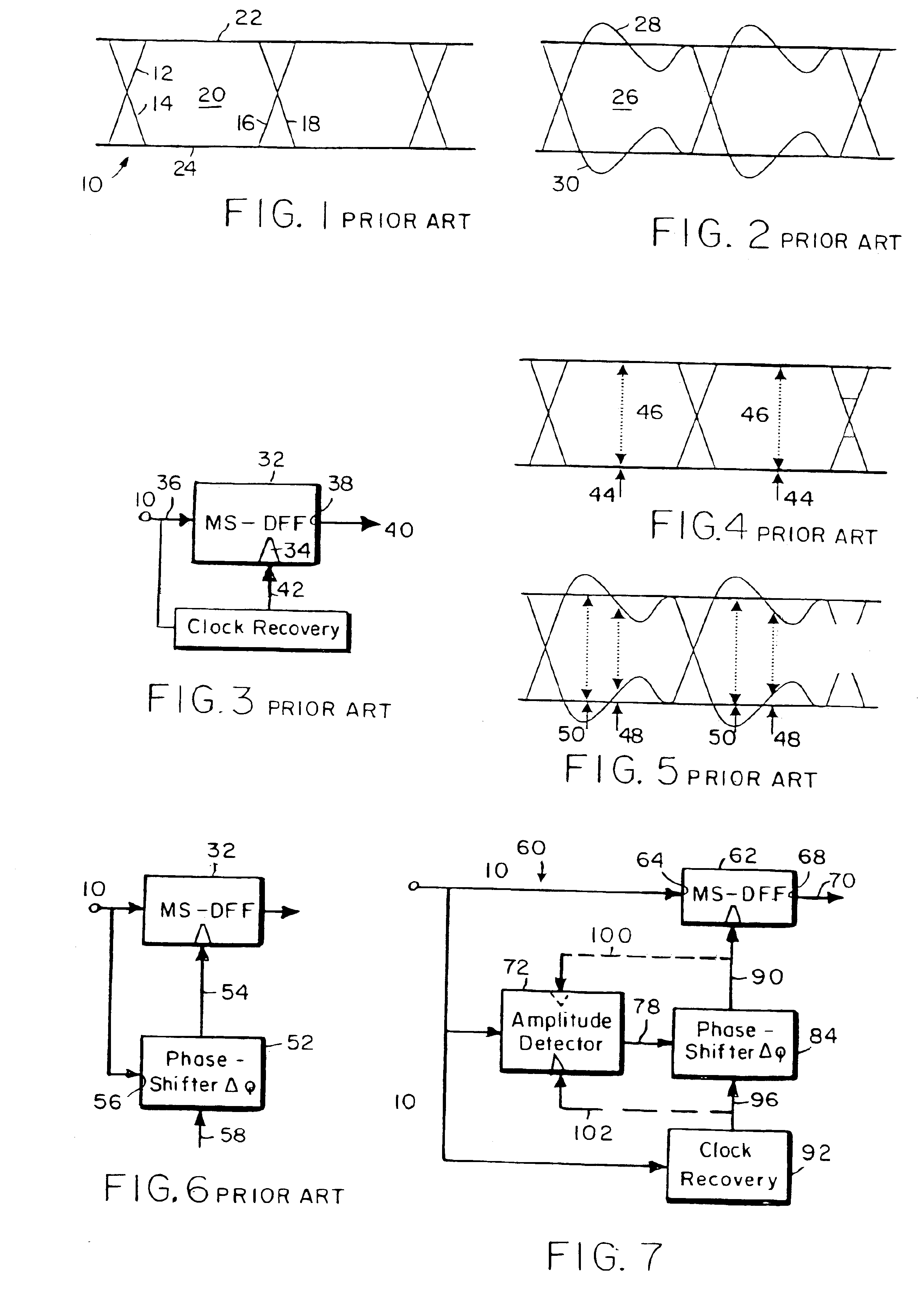
[0033]The data recovery circuit 60 of FIG. 7 shows two alternative embodiments for adjusting the phase shifter 84 so that the decision instant of the master-slave D-type flip-flop 62 coincides with the instant of maximum vertical eye opening 50. In a first embodiment, indicated in FIG. 7 by the lightly dotted line 100, the amplitude detector 72 measures the eye shape and, during this process, controls the phase shifter 84. The amplitude detector 72, together with the phase shifter 84, form a feedback loop, since the phase-shifted clock signal 90 is fed back as the clock input of the amplitude detector 72.

[0034]In a second embodiment, the amplitude detector 72 measures the eye shape and afterwards adjusts the phase-shifter 84. This embodiment does not utilize a feedback loop. The recovered clock signal 96 is supplied to the amplitude detector 72 along a dotted line 102. In the second embodiment, the data recovery circuit 60 engages in an iterative process of sampling the analog input...

second embodiment

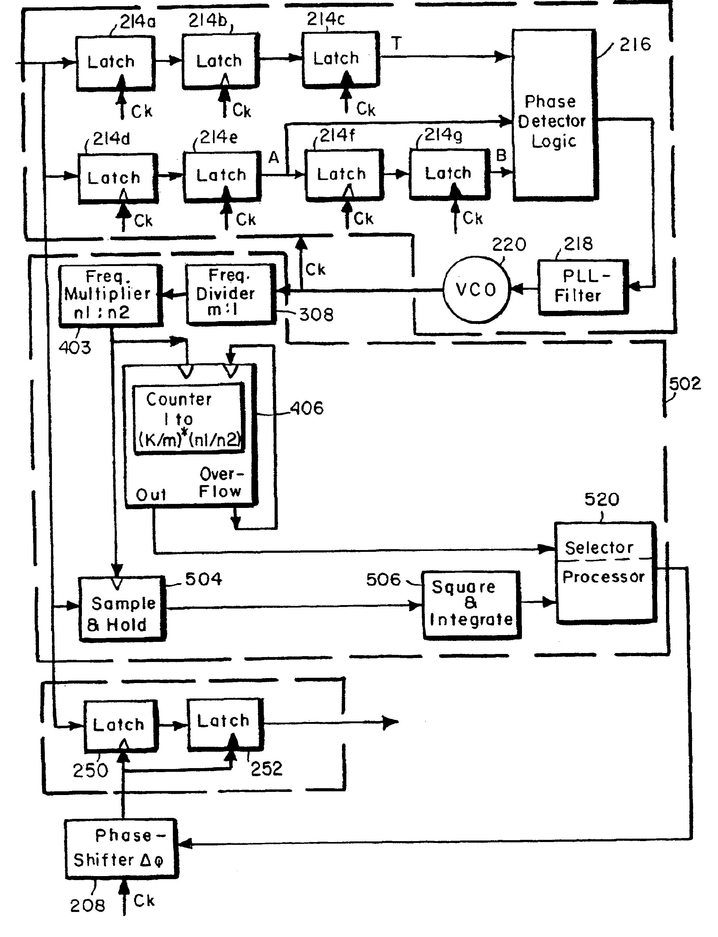
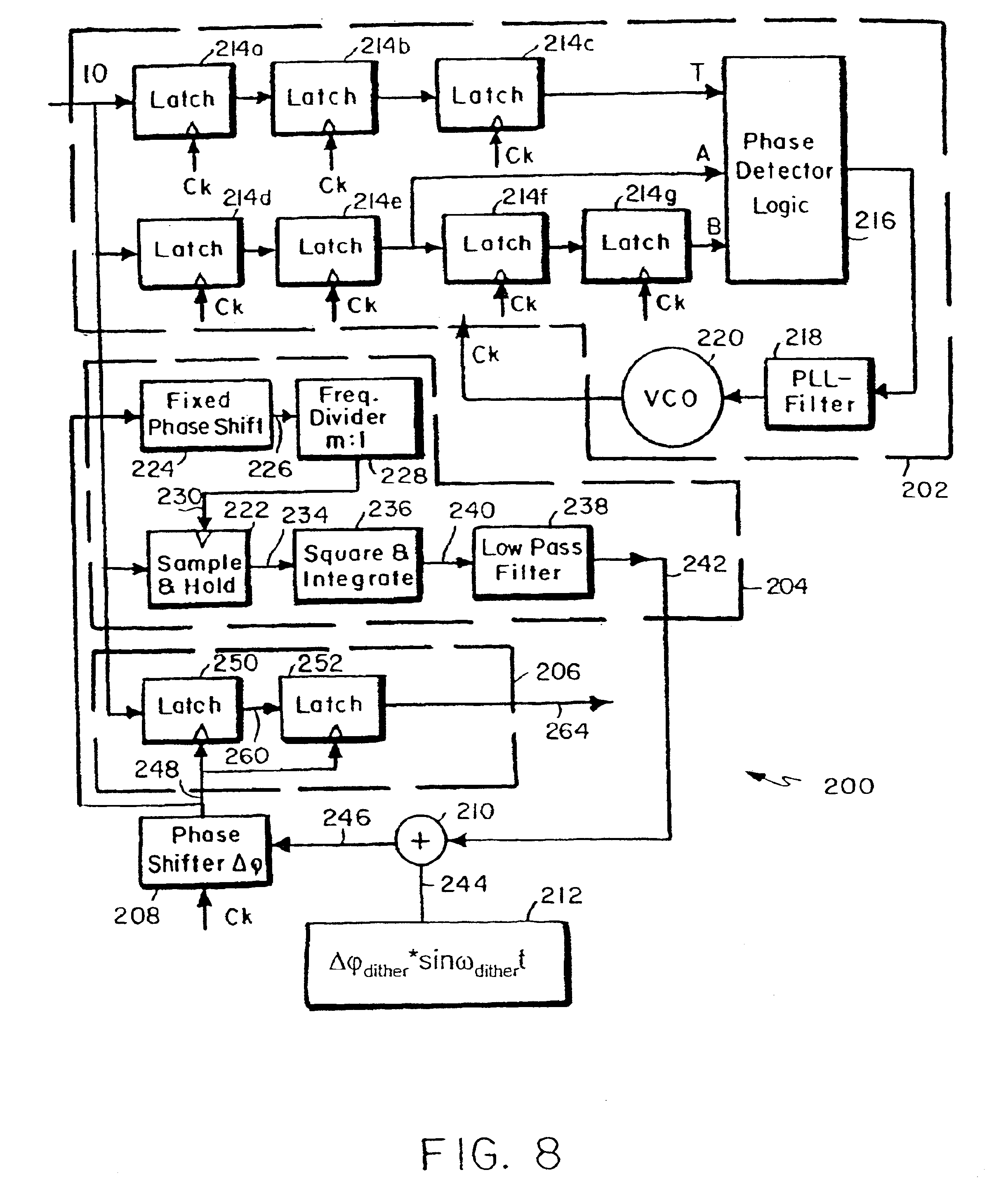
[0045]Turning now to FIG. 9, a data recovery circuit 300 is disclosed. The data recovery circuit 300 is directed to the non feed back embodiment in which Amplitude detector 72 is controlled by an output of clock recovery circuit 92. Like numerals are utilized to indicate like structure, the primary difference being the construction of the amplitude detector. Specifically, data recovery circuit 300 includes the clock recovery circuit 202, the master-slave D-type flip-flop 206, and the phase shifter circuit 208, all the same as described hereinbefore with respect to the circuit of FIG. 8. However, it is to be noted that in the embodiment of FIG. 9, the recovered clock signal Ck is supplied not only to the latches 214a-214g, but also to the amplitude detector circuit 302, as will be discussed more fully hereinbelow.

[0046]An amplitude detector circuit 302 comprises a plurality n of parallel sample and hold circuits 304a-304n. The recovered clock signal 302 Ck is supplied to a frequency ...


PUM

PropertyMeasurementUnit
phaseaaaaaaaaaa
speedaaaaaaaaaa
phase shiftaaaaaaaaaa

Abstract

A circuit for generating a digital data signal from an analog input data signal is disclosed. The circuit comprises a master-slave flip-flop with a clock input for receiving the analog input data signal, an amplitude detecting circuit for detecting the amplitude of the analog input data signal and generating an amplitude detection signal in response thereto, and a phase shifting circuit responsive to the amplitude detection signal for supplying a phase shifted signal to the clock input of the master-slave flip-flop. The circuit may further include a clock recovery circuit for generating a recovered clock signal from a clock signal contained in the analog input data signal. The recovered clock signal may be supplied to the amplitude detecting circuit, or a feedback loop may supply the phase shifted clock signal to the amplitude detecting circuit.

Description

CROSS REFERENCE TO RELATED APPLICATIONS[0001]Priority is claimed from provisional application Ser. No. 60 / 288,374, filed May 3, 2001.FIELD OF THE INVENTION[0002]This invention relates to data recovery circuits, and more particularly, to a circuit for recovering digital data from an analog input data signal.BACKGROUND OF THE INVENTION[0003]The Internet is fundamentally changing the face of networking. Network traffic grows greater and greater each year. Network providers need optical transport solutions that provide high volume channel count, capacity per channel, optical link distance, and sufficient physical space in order to carry the increased traffic.[0004]Current state of the art networks provide 10 Gb / s (Gigabit per second) capacity per optical channel. However, this is not expected to provide sufficient bandwidth to carry projected traffic on the Internet. The next step is believed to be an increase to a 40 Gb / s per channel high-speed fiber-optic communication system.[0005]In...

Claims


Application Information

Patent Timeline
Patent Type & Authority Patents(United States)
IPC IPC(8): H03L7/06H03L7/00H04L7/02H04L7/033G11B20/10G11B20/14H03L7/081
CPCH03L7/00H03L7/06H03L7/081H04L7/007H04L7/033H04L7/0037H04L7/0337
Inventor REINHOLD, MARIOROSE, EDUARDKUNZ, FRANK
Owner CISCO TECH INC
Why Eureka
Try Eureka