
Printing apparatus and method

Inactive Publication Date: 2005-08-23
HEWLETT PACKARD DEV CO LP
View PDF43 Cites 20 Cited by
  • Summary
  • Abstract
  • Description
  • Claims
  • Application Information

AI Technical Summary

Benefits of technology

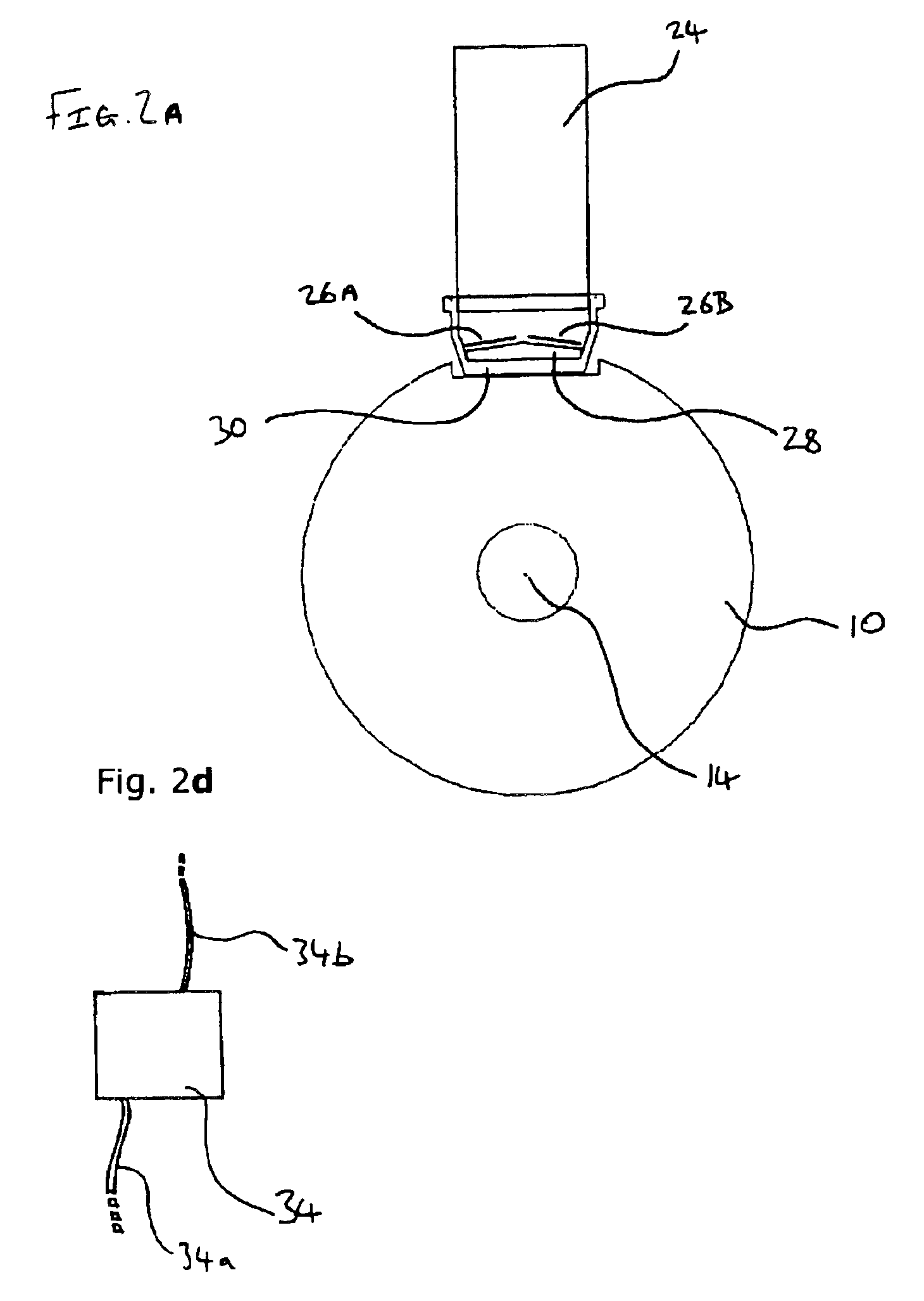
[0009]According to one aspect of the present invention, there is provided an inkjet printing device comprising a drum platen, the platen having a spittoon disposed in the surface of the drum. Advantageously, by locating a spittoon in the surface of the drum, the rotation of the drum relative to the inkjet nozzles of the printer may bring both the spittoon and the image receiving surface associated with the drum, for example a sheet of print media, into a position adjacent the inkjet nozzles in an alternating manner. Thus, the inkjet nozzles may print a print job onto the image receiving surface and spit into the spittoon from substantially the same position. Thus, the printhead(s), which may be in the form of a print bar, for example, may be controlled to implement a spitting routine, and / or other servicing routine, without having to be moved relative to the drum platen.
[0011]In one embodiment, the spittoon is formed by a narrow recess, filled with ink absorbing foam, located in the circumferential surface of the drum. In such an embodiment, as the drum revolves, the recess may periodically pass adjacent the inkjet nozzles allowing the nozzles to spit. Whilst the recess is not adjacent the nozzles, the nozzles may print on an image receiving surface of the drum. In this manner, the spitting process may be implemented whilst the drum continues to rotate at the normal rotational velocity used for printing. Furthermore, since no complex movement is required between the printhead(s) and the drum, embodiments of the invention may benefit from having a relatively simple, reliable and inexpensive chassis structure supporting the drum and printhead(s). The relative positions of the axis of rotation of the drum relative to the printhead(s) may be fixed. Furthermore, such a chassis structure may facilitate the maintenance of an accurate pen-to-paper spacing, which in turn may help to ensure high print quality. Additionally, the space taken up by a printers of embodiments of the present invention may be small compared to systems in which printhead(s) must be moved, for example lifted or translated, relative to the drum in order to allow servicing.

Problems solved by technology

Although such page wide array systems offer the possibility of increased throughput, they suffer from certain disadvantages.
However, the print bars of page wide printer systems are generally bulky.
Thus, moving such print bars to a service station spaced apart from the media feed path tends to increase the working volume of the printer system and the complexity of servicing operations.

Method used


Image

  • Printing apparatus and method
  • Printing apparatus and method
  • Printing apparatus and method

Examples


first embodiment

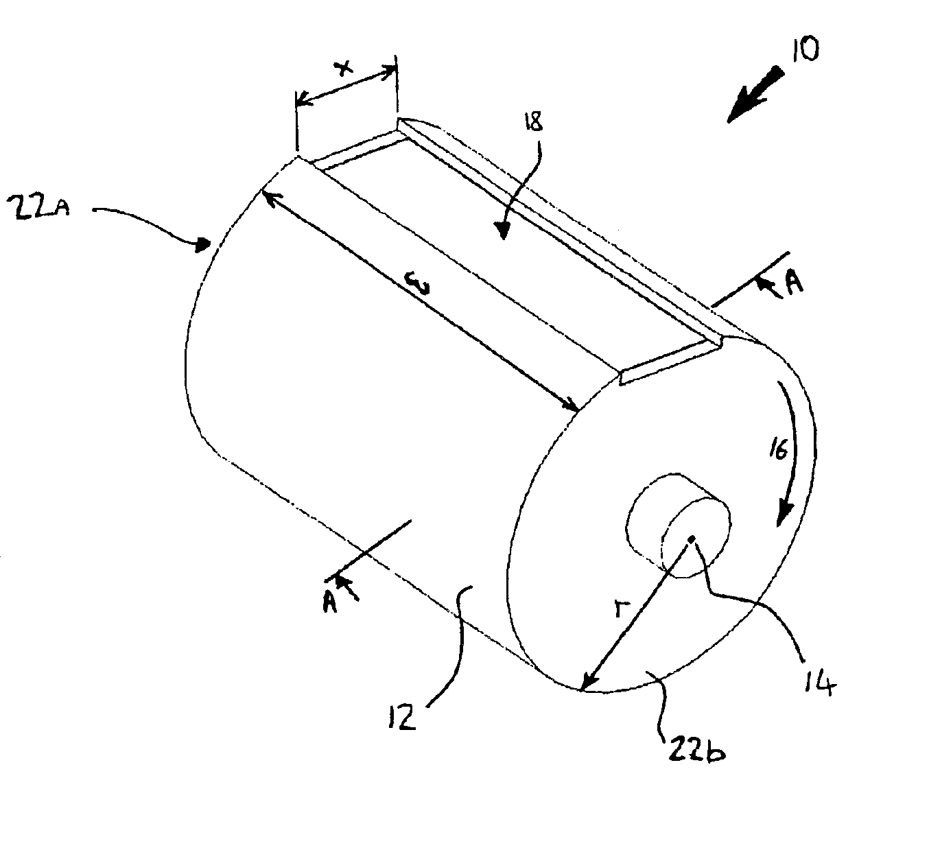
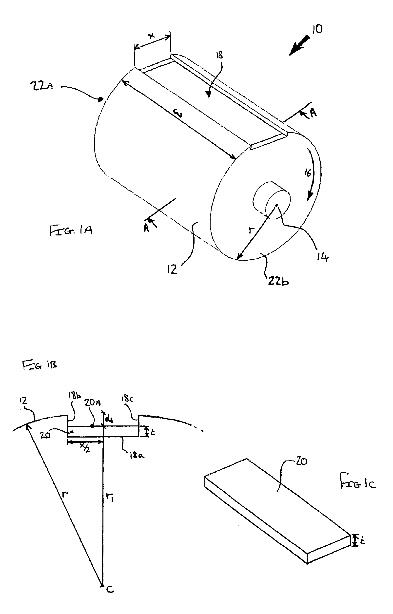
[0024]Referring to the figures, an embodiment of the present invention will now be described. FIG. 1a illustrates a perspective view of a drum platen 10 according to the present embodiment. The drum 10 has a circumferential surface 12, arranged to support print media so that it may be conveyed past an array of inkjet nozzles, illustrated in FIG. 2. The drum has a central shaft or axis 14 about which it is arranged to be driven in the direction of the arrow 16, using a conventional drive mechanism. The drum has a width “w” and its circumferential surface 12 is disposed about the central axis 14 at a radial distance “r”. The drum may be supported in a conventional printer chassis (not shown).

[0025]As can be seen from FIG. 1a, the circumferential surface 12 of the drum 10 is recessed over an area 18. In the present embodiment, the recessed area 18 is rectangular with its length lying parallel with the drum's central axis 14 and extending across the entire width “w” of the circumferenti...


PUM


Abstract

A inkjet printing device comprising a drum platen, the platen having a recess in its circumferential surface. The recess is adapted to accept an inkjet servicing device. The inkjet servicing device, for example a spittoon, may be permanently or semi-permanently located in the recess. Alternatively, The inkjet servicing device, for example a printhead wiper element, may from time to time pass into or through the recess.

Description

CROSS-REFERENCE TO RELATED PATENT APPLICATIONS[0001]The present application is related to co-pending U.S. patent application Ser. No. 10 / 382,650 filed on Mar. 6, 2003 by Bruce G. Johnson, the full disclosure of which is hereby incorporated by reference.FIELD OF THE INVENTION[0002]The present invention relates generally to hardcopy devices and methods, particularly but not exclusively to inkjet printers and to methods of servicing inkjet printers.BACKGROUND OF THE INVENTION[0003]As is well known in the art, conventional inkjet printers generally employ one or more inkjet cartridges, often called “pens”, which eject drops of ink onto a page or sheet of print media. For instance, two earlier thermal ink ejection mechanisms are shown in U.S. Pat. Nos. 5,278,584 and 4,683,481, both assigned to Hewlett-Packard Company. Historically, the pens are usually mounted on a carriage, which is arranged to scan across a scan axis relative to a sheet of print media as the pens print a series of indi...

Claims


Application Information

Patent Timeline
IPC IPC(8): B41J2/165
CPCB41J2/16508
Inventor MONCLUS, ANTONIOURRUTIA, MARTINVALERO, JUAN MANUEL
Owner HEWLETT PACKARD DEV CO LP
Learn More