Eureka AIR delivers breakthrough ideas for toughest innovation challenges, trusted by R&D personnel around the world.

Vanity lighting system

Inactive Publication Date: 2005-08-23
DUALUME CABINETAB
View PDF12 Cites 16 Cited by
  • Summary
  • Abstract
  • Description
  • Claims
  • Application Information

AI Technical Summary

Benefits of technology

[0007]It is a primary object of the present invention to provide a light apparatus which can be either built into a wall or attached thereto, can be used with wall mounted and vanity mirrors, medicine cabinets and the like and provides sufficient light for common tasks such as shaving or applying make-up.
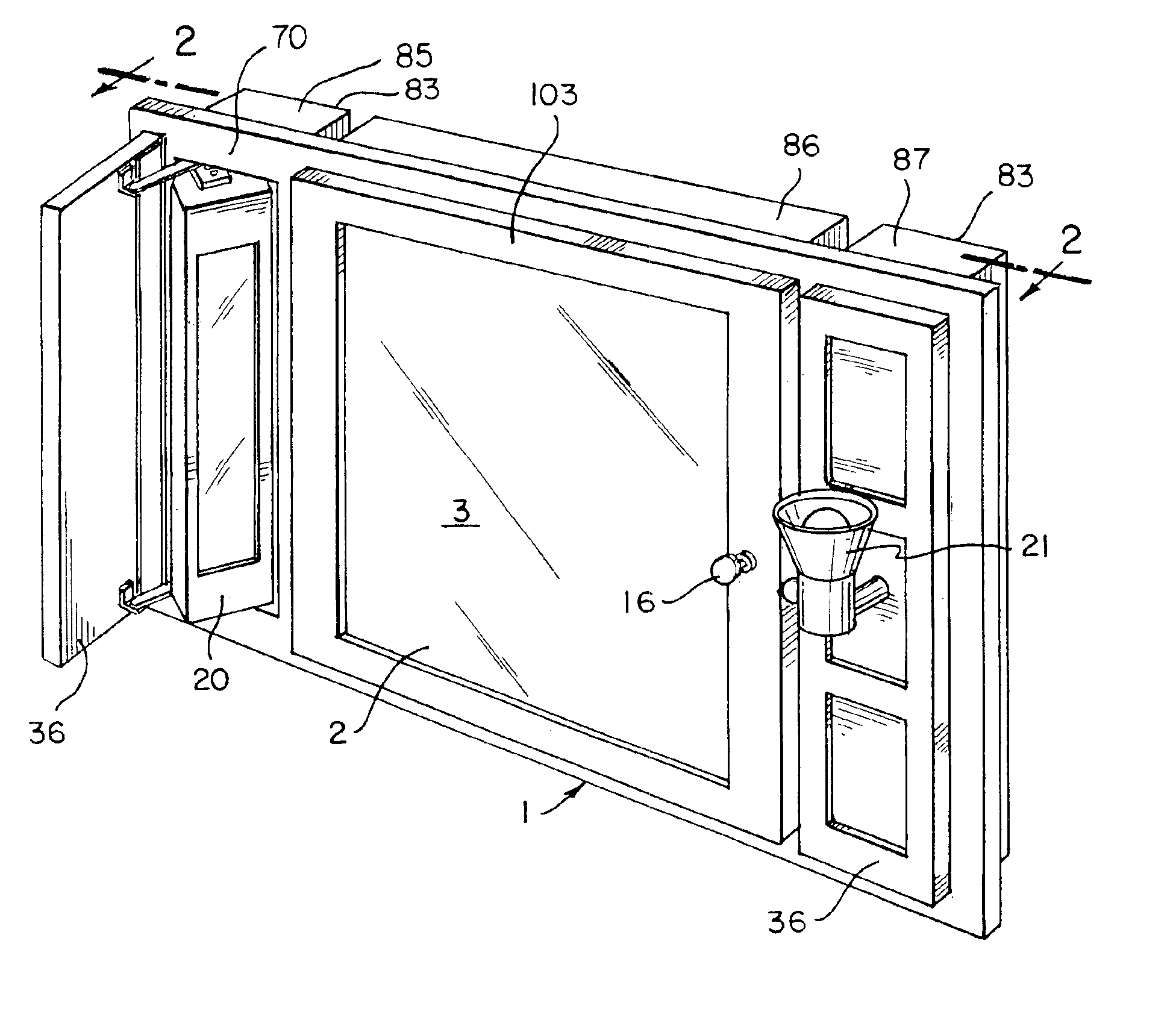
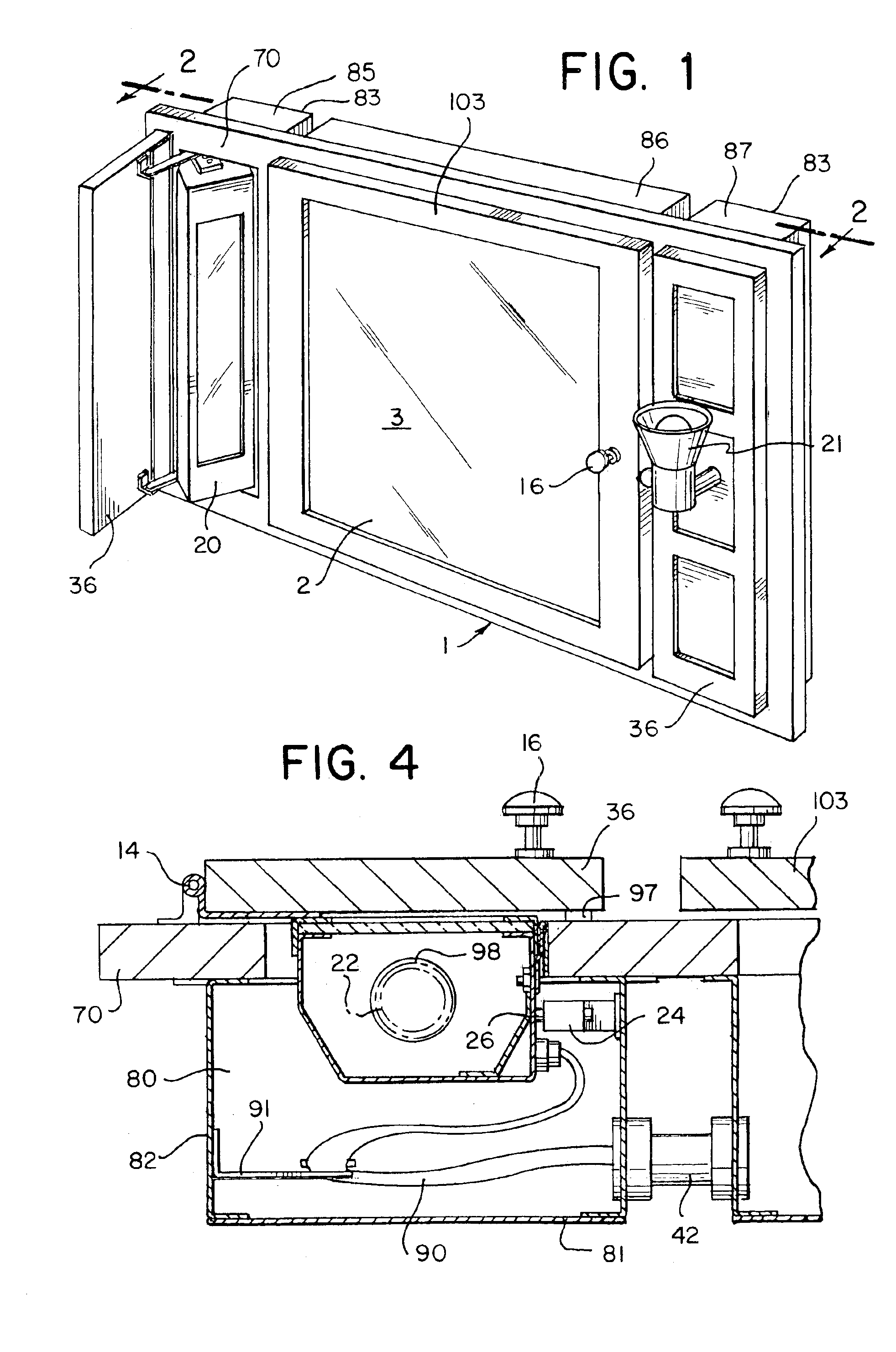
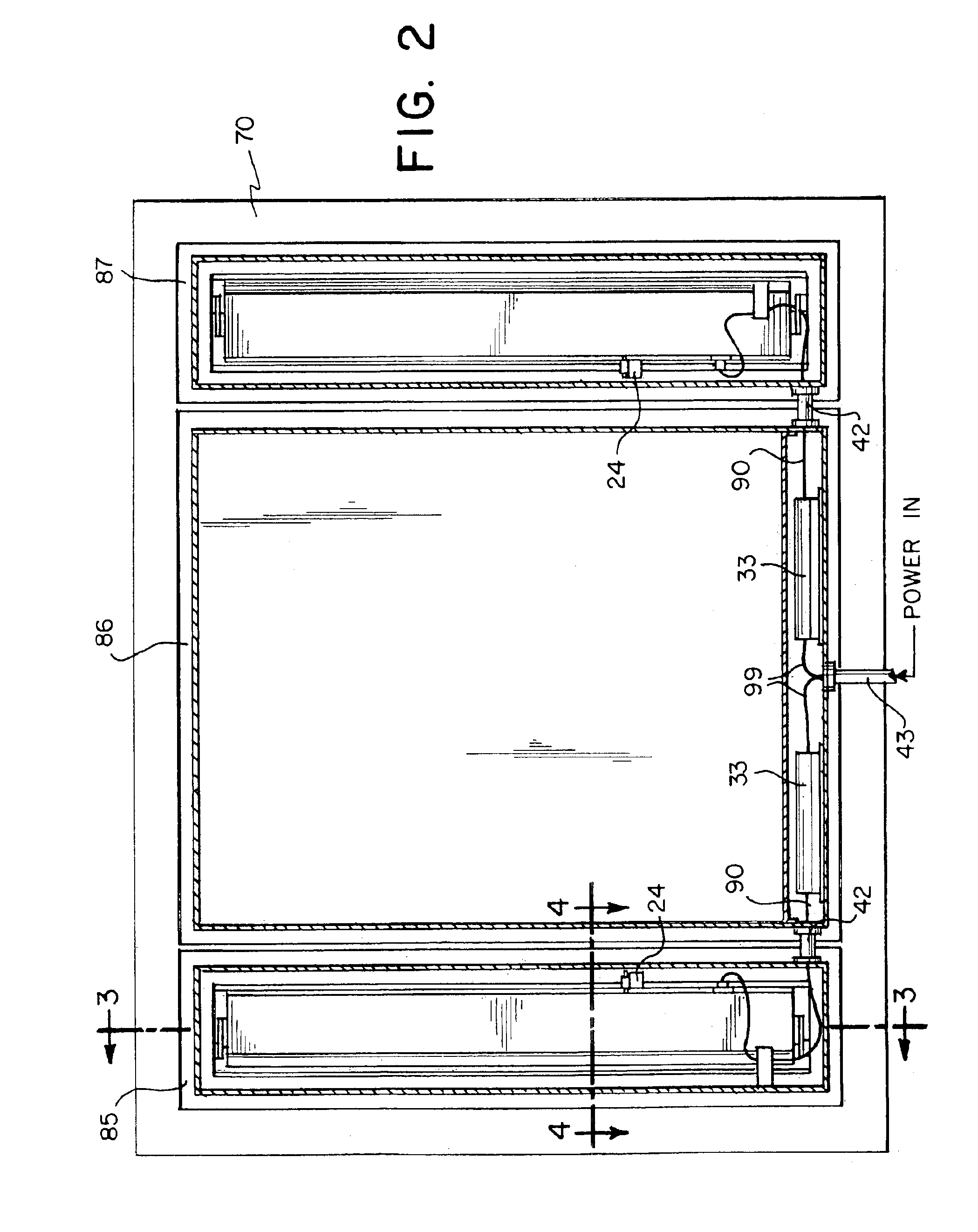
[0009]The present invention is designed to overcome certain problems with prior art vanity lighting systems such as those noted above. This invention includes a vanity lighting system for concealing a lighting apparatus when a pivotally mounted cover is closed and positioning the lighting apparatus through movement of the cover as it is opened. The lighting apparatus includes at least one light bulb and is configured for retention in a viewing position which can be adjusted with movement of the cover. Therefore, adjustment of the lighting apparatus to enhance viewing by different users in different positions from the mirror can be easily achieved.

Problems solved by technology

Parrott and Culver suffer from numerous deficiencies making them undesirable from various standpoints.
For example, in both Parrott and Culver, adjustment of the position of the light source and its angular alignment with respect to the mirror is severely limited.
Furthermore, adjustment of the mirror is cumbersome, requiring the loosening of screws which hold the mirror in a fixed position, realigning the mirror and then retightening the screws.
Flexibility in Culver is limited as well because none of Culver's structures are designed for wall mounting as units in modem, vanity cabinets.
Accordingly, it is virtually impossible to control the angle at which the bulb projects light toward the mirror.
If Parrott's cover were partially pivoted to a position where the cover was between a fully open and closed position, illumination is limited to the portion of the light source that extends through the housing.

Method used


Image

  • Vanity lighting system
  • Vanity lighting system
  • Vanity lighting system

Examples


Embodiment Construction

[0022]The following description is presented to enable any person skilled in the art to make and use the invention. Various modifications to the disclosed embodiments will be readily apparent to those skilled in the art and the general principles defined herein may be applied to other embodiments and applications without departing from the spirit and scope of the present invention. Thus, the present invention is not intended to be limited to the embodiments shown, but is to be accorded the widest scope consistent with the principles and features disclosed herein.

[0023]The present invention provides an improved vanity lighting system. As shown in FIG. 1, one arrangement of a vanity lighting system includes lamp 20 located at the side of a mirror 2. Alternatively, this lamp may be located at the top or bottom of mirror 2 and mirror 2 may be planar or curved for magnification. Numeral 3 indicates the front face of mirror 2 and will be used hereinafter to reference this front face. An a...


PUM


Abstract

A vanity lighting system for concealing a lighting apparatus when a pivotally mounted cover is closed and positioning the lighting apparatus through movement of the cover as it is opened. The vanity lighting apparatus comprises a housing providing an opening, a mirror; an illumination lamp located within the housing, a cover pivotably movable between a closed position overlaying the opening and an open position at least partially spaced from the opening. The cover encloses the lamp such that when the cover is in the closed position the lamp is hidden from view. Additionally, the vanity lighting apparatus comprises a first support assembly including at least two pivotal points operably coupled with the cover and the lamp and a second support assembly including at least one pivotable point operably coupled with the housing and the lamp, wherein the first and second support assemblies provide movement of the lamp in response to the movement of the cover. An activation means is provided for activating and deactivating the illumination lamp in response to the movement of the cover.

Description

FIELD OF INVENTION[0001]The present invention relates to lighting structures and, more particularly, to a concealable lighting apparatus for use with a vanity or wall mounted mirror which can be positioned at a plurality of angles with respect to the mirror. This lighting apparatus may be used in a bathroom, dressing room or other area where supplemental light is required.BACKGROUND OF THE INVENTION[0002]Various lighting arrangements are known for bathrooms and the like. Conventionally, a lighting arrangement is either fixed above, below or at the sides of a wall mounted mirror. These lights are generally exposed at all times or selectively hidden from view by a cover. Various types of vanity cabinet and mirror structures include panels or covers which can be slidably, pivotable, or removably opened to reveal a lighting arrangement for illumination when a person is positioned in front of the cabinet or mirror.[0003]For instance, vanity light apparatus' are shown in U.S. Pat. No. 4,7...

Claims


Application Information

Patent Timeline
IPC IPC(8): F21V33/00A47G1/02F21V21/30
CPCA47G1/02F21S8/028F21V33/004A47B2220/0077F21V21/30F21W2131/302
Inventor HORN, DONALD N.
Owner DUALUME CABINETAB
Why Eureka
Eureka Blog
Learn More