Adapter for human breast pumps

a technology for adapters and breast pumps, applied in the direction of milking pumps, suction devices, intravenous devices, etc., can solve the problem that the pump cannot be used with the whittlestone breast cup assemblies

Inactive Publication Date: 2005-08-23
CLUTE L JASON
View PDF9 Cites 16 Cited by
  • Summary
  • Abstract
  • Description
  • Claims
  • Application Information

AI Technical Summary

Problems solved by technology

However, these pumps could not be used with the Whittlestone breast cup assemblies because the Whittlestone breast cup assemblies require two types of pneumatic power.

Method used


Image

  • Adapter for human breast pumps
  • Adapter for human breast pumps
  • Adapter for human breast pumps

Examples


Embodiment Construction

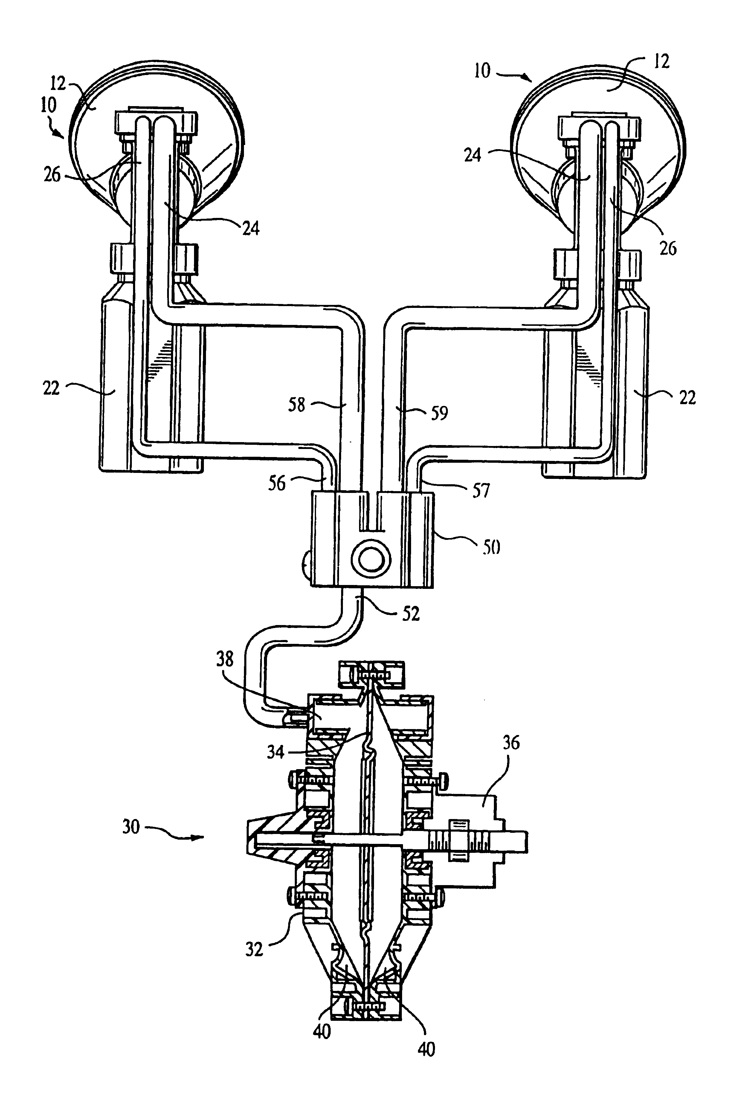
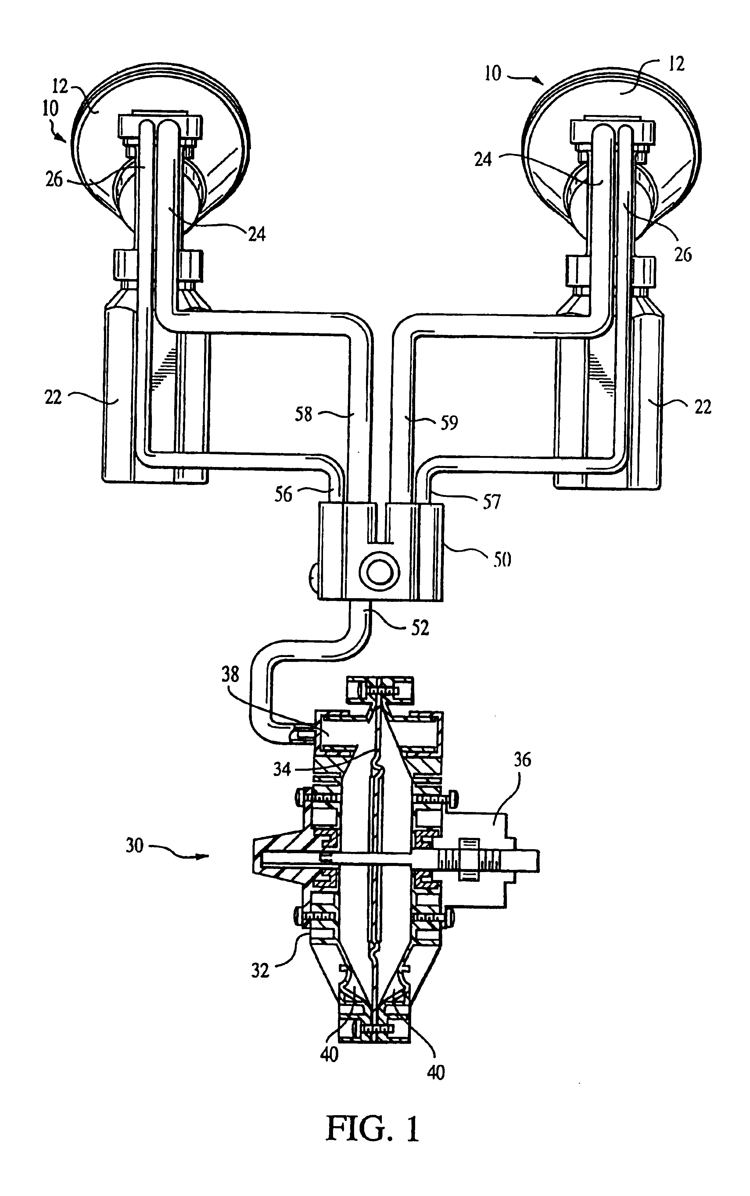
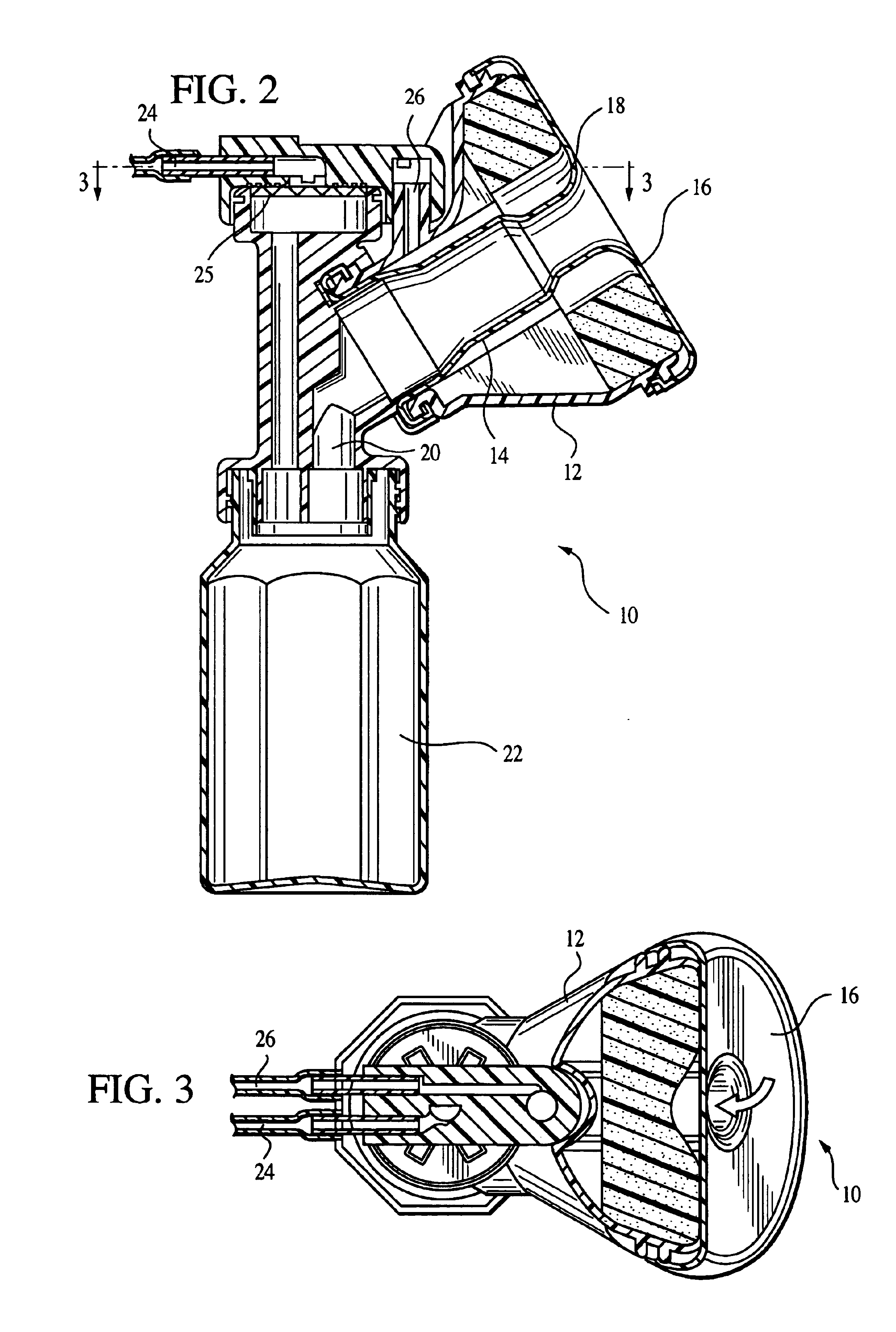
[0025]As seen in FIGS. 1 through 4, a pair of breast cup (express) kits 10 each include a cup 12 and a liner 14. The liner 14 is secured on both ends of the cup to form a breast chamber 16 (when a breast is inserted into the cup) and a pulsation chamber 18. An outlet 20 is provided to remove milk expressed from the breast and deposit the milk in a collector 22.

[0026]The milk is drawn from the breast by a vacuum provided at an inlet 24. A filter 25 may be provided, if desired, to prevent or reduce contamination of the pump, which will be described. The filter 25 may be any suitable device, but is preferably substantially permeable to air when the filter is dry or wet, and substantially impermeable to liquid.

[0027]Pulsating pressure is applied to the pulsation chamber 18 through a pulsation input 26. The pulsating pressure is intermittently negative, or bi-directional. The pulsation pressure, in combination with the vacuum pressure applied to the breast in the breast chamber, opens an...


PUM


Abstract

An air circuit is disclosed that communicates with a cycling, bi-directional or intermittent pressure source, splitting the output of the pressure source into two channels. One channel continues to cycle bi-directional or intermittent pressure, and a second channel employs a one-way valve allowing output of vacuum only. In one embodiment, this circuit can be used to actuate unidirectional, pulsating human breast milk expression devices that use vacuum to draw milk, while massaging the breast with pulsating pressure. The air circuit preferably includes an additional one-way valve, which is located upstream of the one-way negative pressure valve, for relief of excess positive pressure within the circuit. The negative channel output of the air circuit can contain a pressure regulation apparatus for end-user control of negative pressure to the expression devices.

Description

[0001]This invention relates to adapters for human breast pumps, and more particularly, to methods and apparatus for operating a lined breast cup kit that requires both pulsating pressure and a separate vacuum source, using a pump having an intermittent or bi-directional pressure source.BACKGROUND OF THE INVENTION[0002]Breast milk can be pumped by human breast pumps, typically with flanges that are pressed to the breasts, as seen in FIG. 6A. In FIG. 6A, a flange 600 is in operable communication with a breast pump 602 that produces pressure intermittently, or cyclically in both the positive and negative aspects, as seen in FIG. 6B. Negative pressure, or vacuum, withdraws the milk, which falls through a tube 603 into a container 604. This process, commonly described as suck and release, is the underlying mechanical means of milk extraction employed by most conventional human breast pumps.[0003]A different breast milk expression device is disclosed in U.S. Pat. No. 4,607,596, issued Au...

Claims


Application Information

Patent Timeline
Patent Type & Authority Patents(United States)
IPC IPC(8): A61M1/06A61M1/00
CPCA61M1/06A61M1/0072A61M1/066A61M1/0037A61M1/0049A61M1/75A61M1/784A61M1/82A61M1/0697
Inventor MCKENDRY, BRUCELEE, SUNG
Owner CLUTE L JASON
Why Eureka
Try Eureka