Method of installation of a laminated stator core stack in the motor casing

a stator core and motor casing technology, applied in the field of motors, can solve the problems of poor coaxiality of stator s and housing s, stator s vibrating, etc., and achieve the effect of simplifying the assembly work of the motor and being convenient to fix

Active Publication Date: 2005-08-23
NIPPON DENSAN CORP
View PDF12 Cites 19 Cited by
  • Summary
  • Abstract
  • Description
  • Claims
  • Application Information

AI Technical Summary

Benefits of technology

[0010]To achieve these objects, according to a first aspect of the invention, there is provide a motor in which the diameter of the core back outer peripheral portion is set to be equal to or shorter than the diameter of an inner peripheral surface of the housing. Therefore, scoring can be prevented from forming in the stator and/or the housing due to contact between the stator and the housing. After the stator is inserted into the housing, a bar-like member is press-fitted between both end surfaces of the stator core stack. As a result, the slot between the end surfaces is expanded by the bar-like member, and a surface pressure is created between the core back outer peripheral portion and the housing inner peripheral surface. Hence, the stator is fixed in the housing.
[0011]According to another aspect of the invention, there is provided another motor in which the diameter of the core back outer peripheral po

Problems solved by technology

That is, if an outer diameter size of the stator S is excessively smaller than an inner diameter size of the housing H, when the stator S is press-fitted into the housing H, a face pressure between an inner peripheral surface of the housing H and a

Method used


Image

  • Method of installation of a laminated stator core stack in the motor casing
  • Method of installation of a laminated stator core stack in the motor casing
  • Method of installation of a laminated stator core stack in the motor casing

Examples


first embodiment

[0029]1. First Embodiment

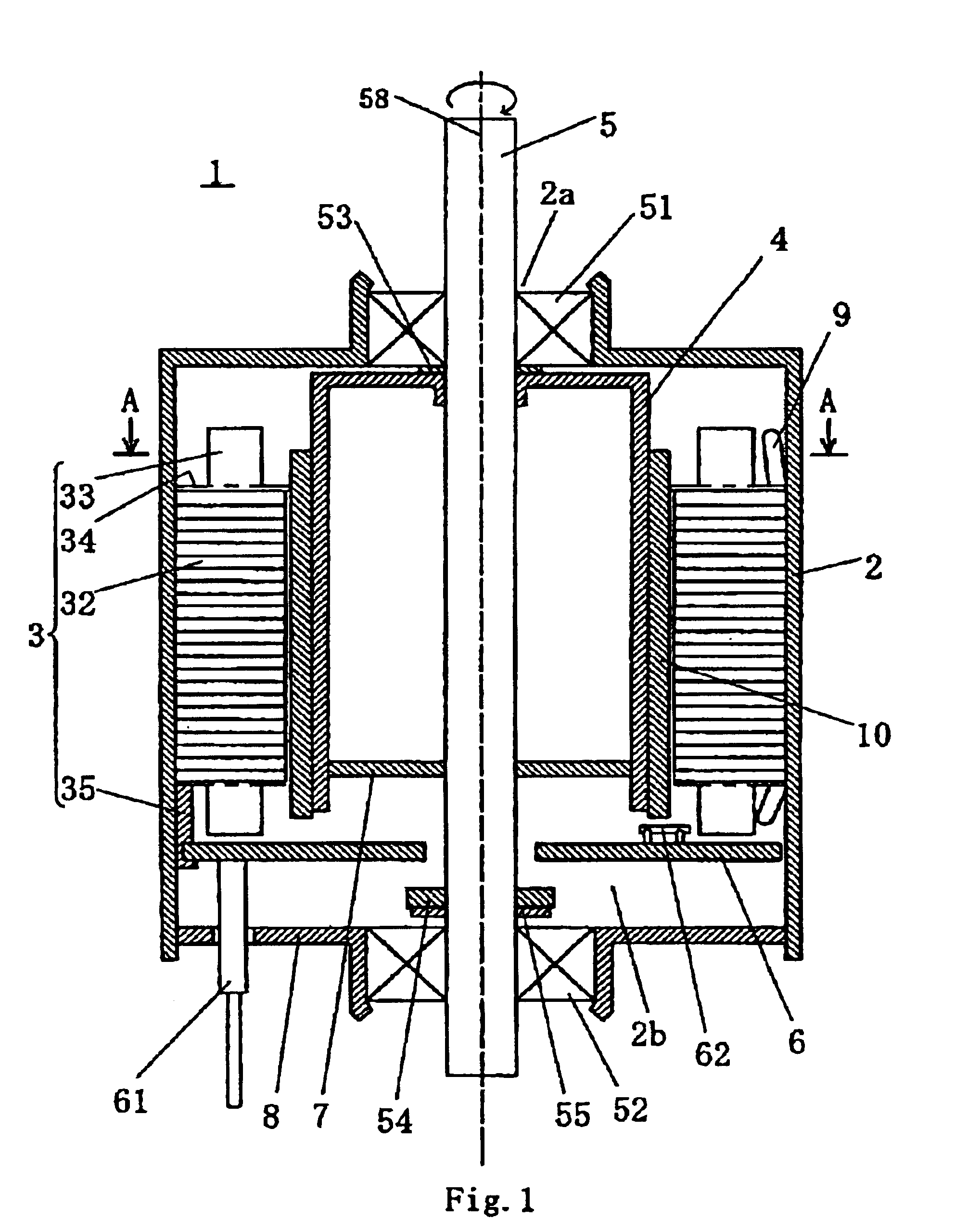
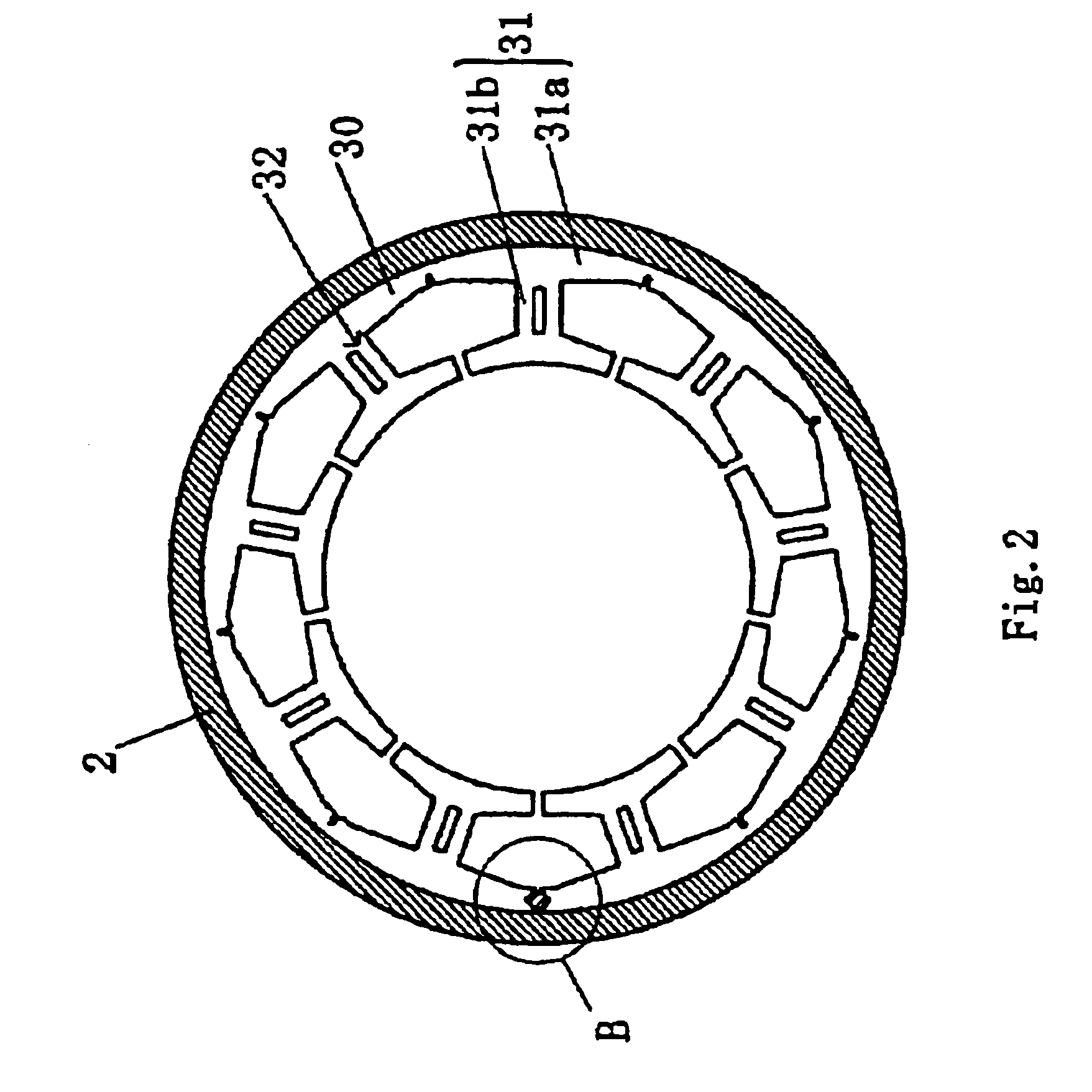
[0030]A motor 1 according to a first embodiment of the invention will be explained below with reference to the accompanying drawings. FIG. 1 is a sectional view in an axial direction showing the motor 1 in the first preferred embodiment, andFIG. 2 is a sectional view of the motor taken along line A—A in FIG. 1. In FIG. 2, peripheral members of a rotary shaft and windings are omitted.

[0031]The motor 1 comprises a cylindrical housing 2 having a small opening portion 2a formed on an upper side in an axial direction which is positioned on the other end side in the axial direction, and a large opening portion 2b with a larger diameter than the small opening portion 2a formed on a lower side in the axial direction which is positioned on one end side in the axial direction, a stator 3 fixed or secured on an inner peripheral surface of the housing 2, a circuit board 6 attached on the stator 3, and a plate 8 attached to the housing 2.

[0032]An upper bearing 51 is fixe...

second embodiment

[0046]2. Second Embodiment

[0047]FIG. 6 is a sectional view in axial direction showing a motor 101 in a second preferred embodiment of the invention. FIG. 7 is a sectional view A—A in FIG. 6. In FIG. 7, peripheral members of the rotary shaft and winding are omitted. The motor 101 in this embodiment is basically similar in structure to the first embodiment, and reference numerals of the corresponding parts are indicated in the basic unit of 100, and only different parts are explained below.

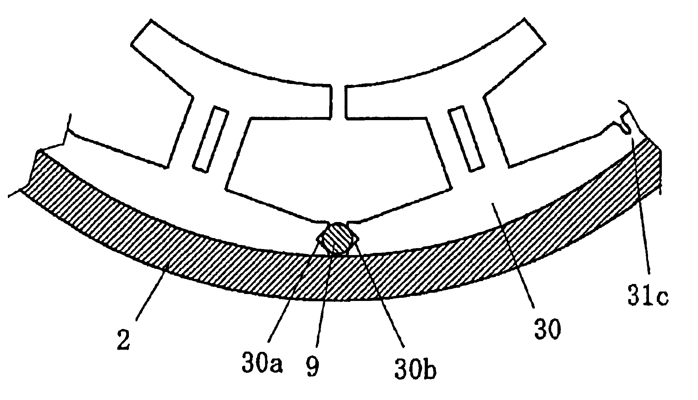
[0048]In this embodiment, as shown in FIG. 8, a notch in plan view is formed in a back side end of core back 131a out of both end surfaces 130a and 130b of core pieces 131A and 131B at both end surfaces of a straight core 130.

[0049]As shown in magnified perspective view and perspective view in FIG. 10 and FIG. 11, on the outer peripheral portion of a housing 102, an engaging portion 21 in a V-shape in plan view is formed to project from the outer peripheral surface of the housing 102 in the radial i...


PUM

PropertyMeasurementUnit
Lengthaaaaaaaaaa
Diameteraaaaaaaaaa
Deformation enthalpyaaaaaaaaaa

Abstract

A stator core stack formed by laminating a plurality of straight cores having a core back, a tooth, and a linking part for linking the core backs. In the stator core stack, the linking portion is folded and deformed the linking portion so as to join an end surfaces of the straight core, and a core back outer peripheral portion is formed at the back side of the core back, and the diameter of the core back outer peripheral portion is formed same as or shorter than the diameter of the inner peripheral surface of the housing, and is disposed in the housing. A bar-like member is press-fitted in the axial direction between both the end surfaces of the straight core. In other example of motor, an engaging portion extending in the axial direction and projecting in the radial inward direction is formed in the inner peripheral surface of the housing, and the end surfaces of the straight core are engaged or fitted with the engaging portion.

Description

CROSS REFERENCE TO RELATED APPLICATION[0001]The disclosure of Japanese Patent Application No.2003-120825 filed Apr. 25, 2003 and No.2004-027506 filed Feb. 4, 2004 including specification, drawings and claims is incorporated herein by reference in its entirety.FIELD OF THE INVENTION[0002]The present invention relates to a motor, and more particularly to an inner rotor type motor.BACKGROUND OF THE INVENTION[0003]Hitherto is known an inner rotor type motor in which a magnet is disposed on an inner peripheral side of a stator. In such an inner rotor type motor, as shown in a plan view in FIG. 14, a plurality of core pieces C1 are coupled by way of thin linking portions, so that a straight core C is formed. The straight core C is a member formed by blanking a flat plate made of magnetic material such a silicon steel plate, and a stator core stack U is formed by laminating a plurality thereof, as shown in a perspective view in FIG. 15. Each core piece has a core back Y and a tooth T. The ...

Claims


Application Information

Patent Timeline
IPC IPC(8): H02K1/14H02K1/18
CPCH02K1/148H02K1/185Y10T29/49009
Inventor FUJII, YOSHIOYAMADA, YOSUKEOTAGAKI, AKIRA
Owner NIPPON DENSAN CORP
Why Eureka
Try Eureka