Electrical liner actuator for lock

a technology of electric liner actuator and lock, which is applied in the field of locks, can solve the problems of possible complete spring compression, large rotation speed error of the motor, and difficult control of the travel of the pin on the rotating shaft, so as to improve the reliability of the mechanism, prevent distortion or bouncing of the spring, and smooth the effect of entering

Inactive Publication Date: 2014-06-03
SHENZHEN SUOZHIDAO TECH
View PDF25 Cites 10 Cited by
  • Summary
  • Abstract
  • Description
  • Claims
  • Application Information

AI Technical Summary

Benefits of technology

[0007]The invention aims to provide an electrical liner actuator for a lock, with high reliability and simple structure.
[0030]Due to the convex shape of the second windings of the spring of the invention, not only the travel of the relative motion of the spring and the pin can be limited by the change of the spiral of the spring but also the pin can smoothly enter into the spiral track of the first winding in the case of reversing rotation through the continuous smooth transition portion between the second winding and the first winding at the end which is not compressed and an inclined gap between the transition portion and a first coil of the first winding in the case of complete compression of the first winding of the spring. Meanwhile, the radial rotation of the slider relative to the spring is limited in virtue of the contact of the second windings and the inner walls of the slider, so that the case that the spring rotates along with the shaft is prevented, thus the reliability of the mechanism is improved.
[0031]The third windings of the invention can absorb and buffer the vibration and impact caused by the pin on the spring when the motor is started and reversed during the abnormal operation of the lock. Moreover, the distortion or bouncing of the spring can also be prevented, so that the pin is assured to smoothly enter into the spiral track of the spring, thus the relative motion between the pin and the spring is more stable and reliable.
[0032]As the pin is formed by bending the steel wire and the extended portion thereof is smooth and has no sharp sides and burrs, not only the spring is prevented from being scored but also the forming or grinding of the extended portion of the pin is saved.

Problems solved by technology

Due to the parameter decentrality during the motor manufacturing and the voltage variation of supplying cells, the rotating speed error of the motor may be large, and the travel of the pin on the rotating shaft is difficult to control even by adopting a reducing gear train and controlling the conduction time.
Particularly, in the case of abnormal unlocking or locking, for example, a lock handle is pulled at the moment or the lock handle is pulled first and then an unlocking command is input when the motion of the clutch mechanism is not in place, common manual operation errors like this will result in the clamping of the slider driven by the spring and then possible complete compression of the spring.
Herein, the friction force is maximized and the extrusion of adjacent turns of the spring is generated, thus not only the spring tends to rotate along the shaft but also the pin cannot enter into a spiral track of the spring when the motor is started counterclockwise, consequently unlocking or locking failures are produced.
As no buffer mechanism is arranged, the spring will jitter or bounce due to the impact of the pin on the spring when the motor is started counterclockwise, thus the failure that the pin cannot smoothly enter into the spiral track of the spring after the rotating shaft changes the rotation direction may be caused, consequently the clutch mechanism for the lock fails.

Method used


Image

  • Electrical liner actuator for lock
  • Electrical liner actuator for lock
  • Electrical liner actuator for lock

Examples


Embodiment Construction

[0054]For those skilled in the art to further understand the invention, detailed description is given below with the attached drawings and embodiments.

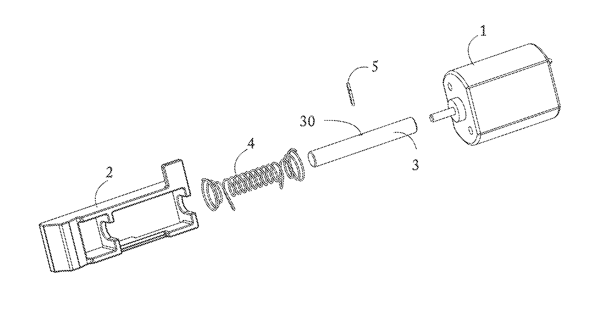
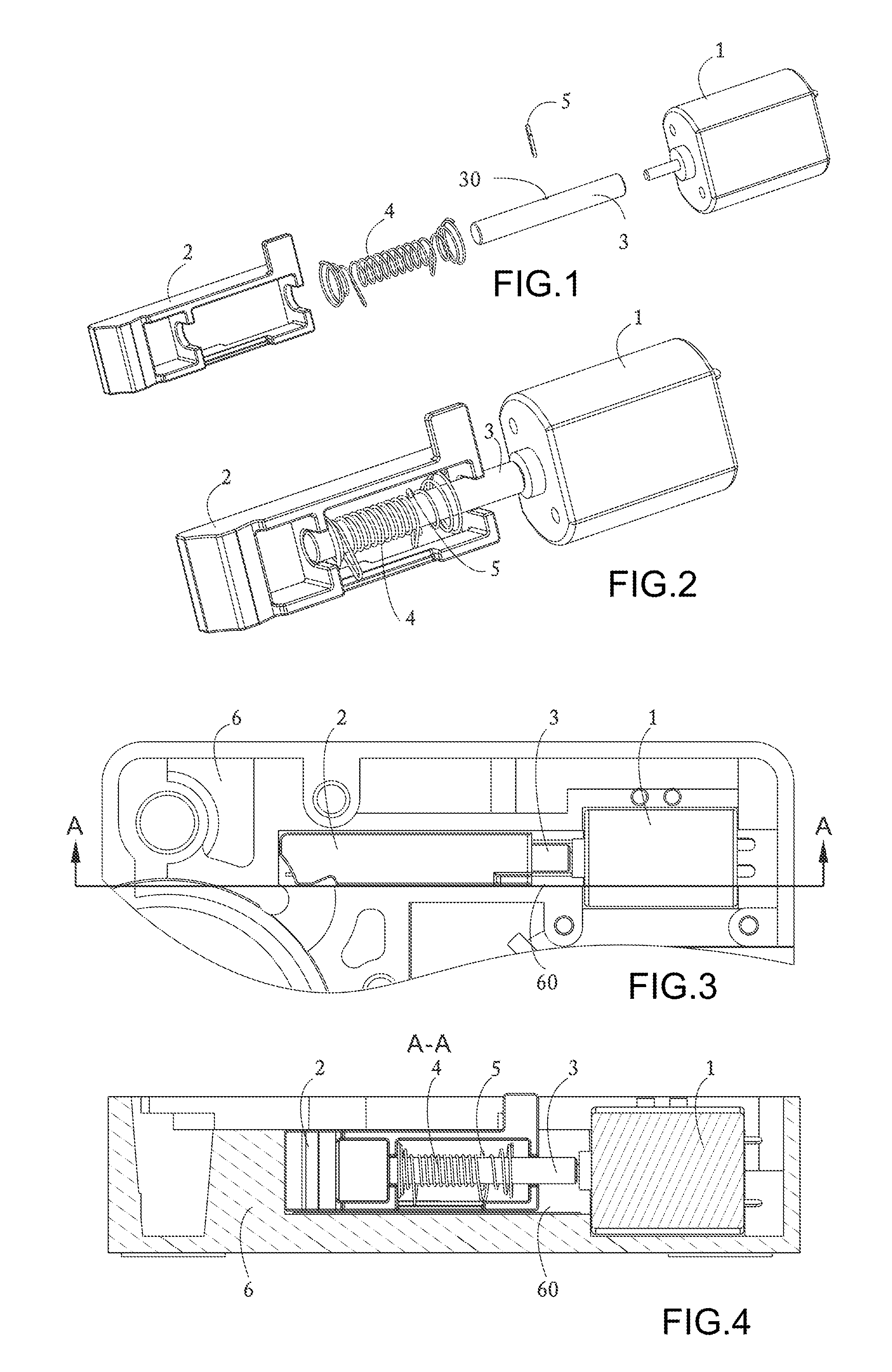
[0055]As illustrated in FIGS. 1 to 4, the electrical liner actuator provided by the invention consists of a motor 1, a slider 2, a rotating shaft 3, a spring 4 and a pin 5, wherein the motor 1 is a common DC micromotor and directly connected with the rotating shaft 3; a hole 30 for fixing the pin 5 is formed on the rotating shaft 3; the spring 4 is sleeved on the rotating shaft; an extended portion of the pin 5 is disposed between two adjacent winding coils of the spring 4; the motor is fixed inside a lock's housing 6; the slider 2 is arranged inside a sliding chute 60 which is arranged inside the lock's housing 6; and the sliding chute has the function of limiting and guiding the slider 2. In the embodiment of the invention, a solid portion 28 is formed at one end of the slider 2 and has the function of blocking the retraction of a l...


PUM


Abstract

The invention relates to an electrical linear actuator for a lock, which comprises a motor, a rotating shaft connected with the motor, a spring sleeved on the rotating shaft and a pin arranged on the rotating shaft and also comprises a slider, wherein the slider is provided with a frame capable of receiving the shaft and the spring; grooves for limiting the rotating shaft are formed on a wall; the spring comprises a first winding, end coils and second windings; the first winding is arranged in the middle part of the spring and takes the shape of a cylindrical spiral; the end coils are respectively arranged at both ends of the spring and coaxial with the first winding; the second windings are arranged between the first winding and the end coils, and circumscribed circles of the second windings are convex relative to the first winding; and third windings coaxial with the first winding can be arranged between the second windings and the end coils.

Description

FIELD OF THE INVENTION[0001]The invention relates to a lock, in particular to an electrical liner actuator for a combination lock.BACKGROUND OF THE INVENTION[0002]The traditional electrically operated lock, in particular a combination lock, commonly uses a lock clutch mechanism driven by a micromotor in order to save the space and reduce the energy consumption. One technical proposal is to adopt a spiral spring sleeved on a rotating shaft and a pin fixed on the rotating shaft, convert the rotary motion of the rotating shaft of the motor into the rectilinear motion between the spring and the pin, and then drive or pull the clutch mechanism or a latching mechanism of the lock to operate, and finally realize the control of the lock.[0003]The U.S. Pat. No. 5,018,375 (Issue Date: Mar. 28, 1991) discloses a lockset having electric means for disabling and enabling the outer handle. The electric means is characterized in that: a transverse pin is arranged on a motor shaft; a spiral spring i...

Claims


Application Information

Patent Timeline
Patent Type & Authority Patents(United States)
IPC IPC(8): E05B47/00
CPCE05B2047/0031E05B2015/0406E05B15/04E05B47/026Y10T70/7102Y10T292/1021Y10T70/7113Y10T70/8027
Inventor YUAN, MENGXIAO
Owner SHENZHEN SUOZHIDAO TECH
Why Eureka
Try Eureka