High bandwidth oscilloscope probe with replaceable cable

a technology of oscilloscope and replaceable cables, applied in the direction of coupling device connections, instruments, measurement instrument housings, etc., can solve the problems of affecting the performance of the oscilloscope probe, the sheath of the active probe is easily abraded, and the active probe is a fairly expensive item as a complete assembly

Inactive Publication Date: 2005-08-23
AGILENT TECH INC
View PDF11 Cites 67 Cited by
  • Summary
  • Abstract
  • Description
  • Claims
  • Application Information

AI Technical Summary

Problems solved by technology

The active probe is, as a complete assembly, a fairly expensive item.
The cable, however, it exposed to, and is susceptible to, forms of mechanical abuse that the stuff in the housings is better able to withstand, owing to the more rugged mechanical nature of the housing.
Its sheath can be abraded to expose the conductors, or it can be accidentally cut, or be burned with a soldering iron.
Destruction often comes from unforeseeable directions: the lab's pet ferret is on the loose, and no self-respecting ferret can resist chewing on a cable.
Sometimes cables get pinched under the foot of a heavy instrument during the movement of equipment.
But now newly measured results that used to be fine are suddenly wrong, for no apparent reason.
Reflections owing to mismatches in the characteristic impedance show up as frequency dependent errors in accuracy.
If the cable has been ruined, then the whole probe has to go in for repair, often at considerable expense and no small amount of time out of service.
But with a conventional probe, even having that does not allow its successful installation.
Getting the crimped ferrule off without damaging the tang is a dicey operation; sometimes the sub-assembly bearing the tang is fatally damaged during an attempt to remove the crimped ferrule.

Method used


Image

  • High bandwidth oscilloscope probe with replaceable cable
  • High bandwidth oscilloscope probe with replaceable cable
  • High bandwidth oscilloscope probe with replaceable cable

Examples


Embodiment Construction

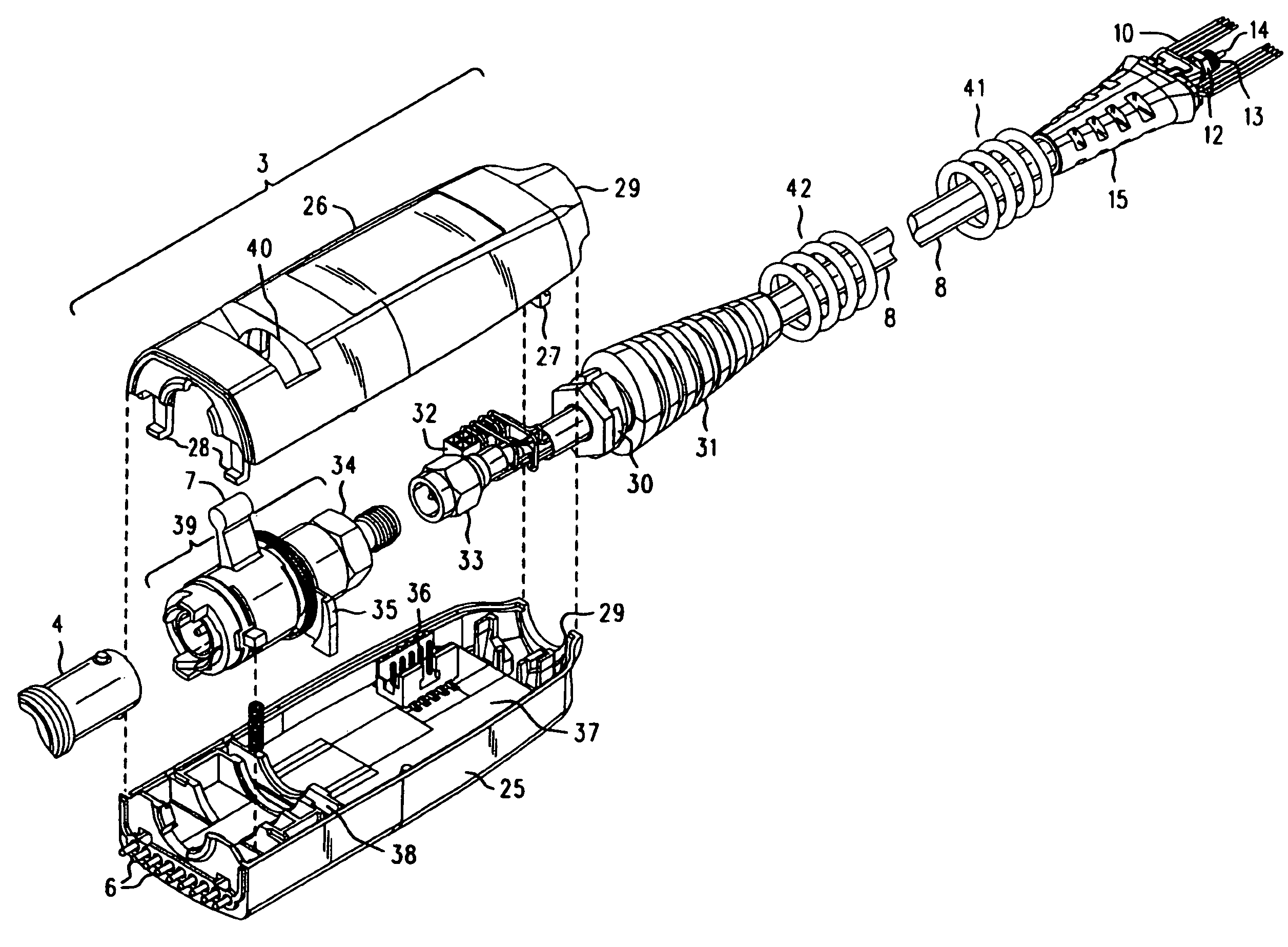
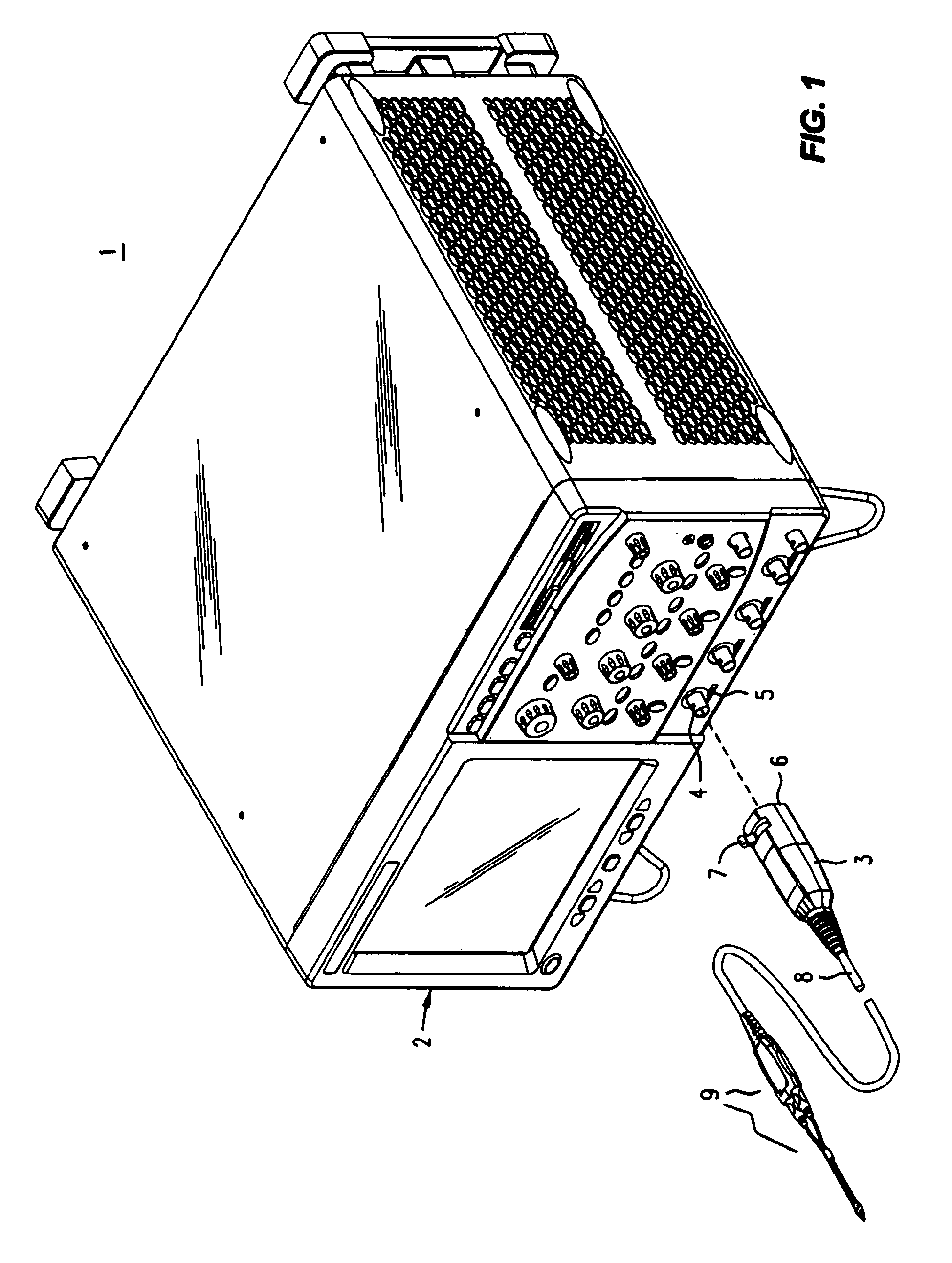
[0019]Refer now to FIG. 1, wherein is shown a front perspective view 1 of an electronic instrument 2, such as a digital oscilloscope, having one or more front panel female BNC connectors 4 that receive a positive locking push-on precision male BNC connector assembly 3 (pod housing), say, in support of operation with an active probe 9 connected at a distal end of a cable 8. In a manner similar to that explained in the incorporated POSITIVE LOCKING PUSH-ON PRECISION BNC CONNECTOR, the positive locking push-on precision BNC connector pod housing is installed by first lining it up and then pushing it toward the 'scope. That engages the BNC detents, and a simple motion with the thumb against the lever 7 performs a positive locking that fully and forcefully mates the two BNC connector halves. When the pod housing 3 is locked, not only is a precision BNC connection established with connector 4, but a row of spring loaded pins 6 (not visible) on the front of the housing for the push-on asse...


PUM


Abstract

A probe pod housing is connected by a cable to an active probe. The probe pod housing carries a male push-on precision BNC connector that is also a cross-series adapter. The center conductor of the cable receives a male connector that then mates with the non-BNC end of the cross-series adapter. Auxiliary conductors that may also be carried by the cable are connected to male pins (soldered to a circuit board carried within the probe pod) with a push-on female in-line connector. The active probe itself uses a soldered-to-the-shield threaded nut technique. The nut threads into a metallic body that contains the impedance converter and that is enclosed by the body of the active probe. The cable is replaced by first unsoldering the center conductor (and also any auxiliary conductors). Then the nut (which is still soldered to the shield) is unscrewed from the metallic body, and the cable is free from the probe. At the probe pod end the cable mounted male connector is simply unscrewed from the cross-series adapter, and any auxiliary conductors disconnected by removing the female wire-mounted in-line connector.

Description

REFERENCE TO RELATED APPLICATIONS[0001]The subject matter of this disclosure is related to, and makes use of, that which is disclosed in U.S. patent application Ser. No. 10 / 764,928 entitled POSITIVE LOCKING PUSH-ON PRECISION BNC CONNECTOR FOR AN OSCILLOSCOPE PROBE, filed 26 Jan. 2004 by James E. Cannon and assigned to Agilent Technologies of Palo Alto, Calif. Because of the similarity in subject matter, and for the sake of brevity in the present case, that US Patent Application is hereby expressly incorporated herein by reference, and will be referred to as “POSITIVE LOCKING PUSH-ON PRECISION BNC CONNECTOR”.[0002]The above incorporated Application itself incorporates U.S. Pat. No. 6,609,925, issued 26 Aug. 2003, entitled PRECISION BNC CONNECTOR, filed 30 Apr. 2002 by James E. Cannon and assigned to Agilent Technologies of Palo Alto, Calif., which for that reason, is also hereby expressly incorporated herein by reference, and will be referred to as “PRECISION BNC CONNECTOR” or as “th...

Claims


Application Information

Patent Timeline
Patent Type & Authority Patents(United States)
IPC IPC(8): H01R13/625G01R1/04G01R1/067G01R1/02
CPCH01R13/625G01R1/04G01R1/06772G01R1/06788H01R24/542H01R2103/00
Inventor CANNON, JAMES E.
Owner AGILENT TECH INC
Why Eureka
Try Eureka