
System for determining an implement arm position

Inactive Publication Date: 2005-08-23
CATERPILLAR INC
View PDF8 Cites 49 Cited by
  • Summary
  • Abstract
  • Description
  • Claims
  • Application Information

AI Technical Summary

Benefits of technology

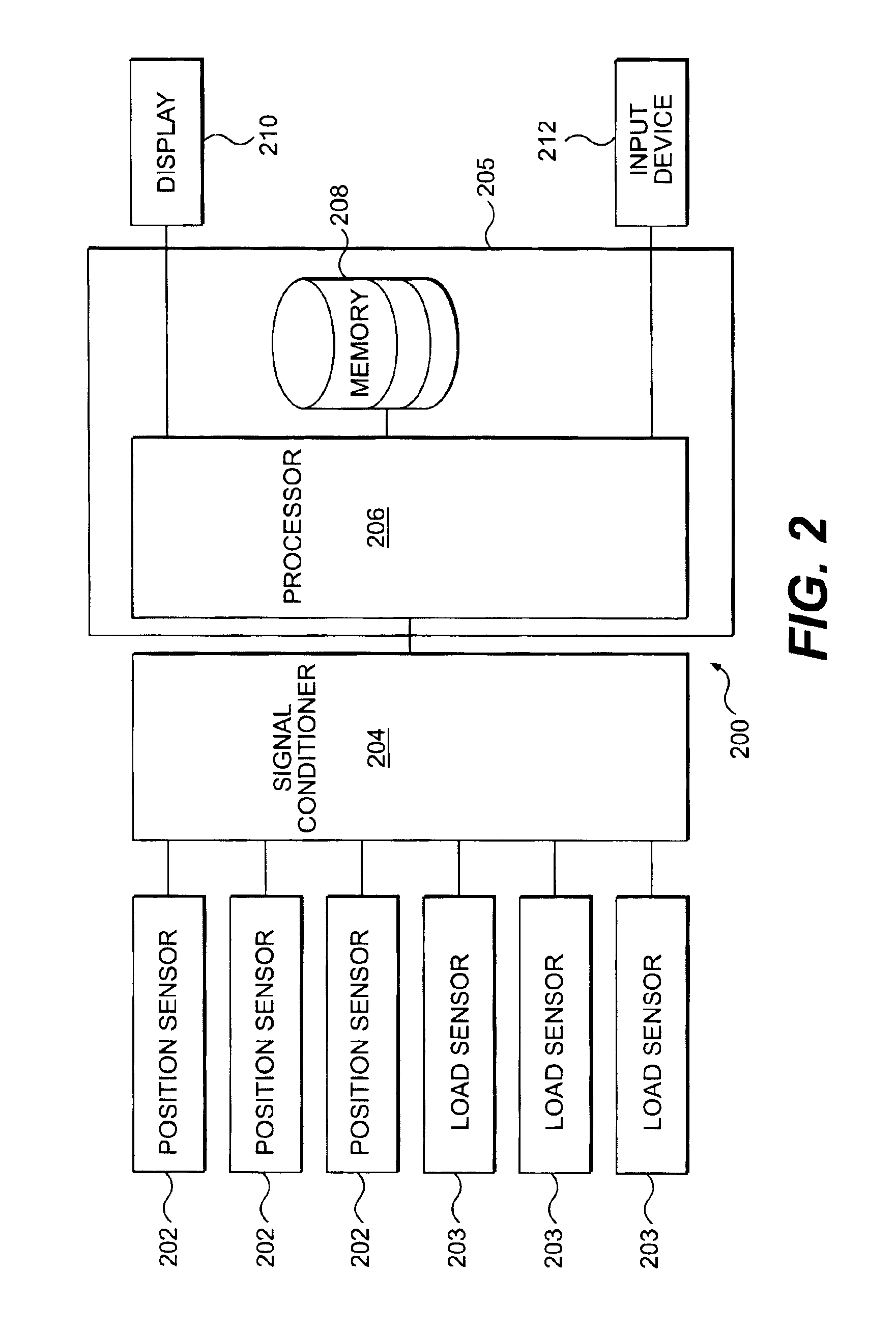
[0007]In one aspect, the present disclosure is directed to a control system for determining a position of an implement arm having a work implement. The implement arm includes mating components connected by at least one joint. The control system includes at least one position sensor operably associated with the implement arm and configured to sense positional aspects of the implement arm. It also includes at least one load sensor operably associated

Problems solved by technology

However, several sources of error may affect the accuracy of the implement arm position determined with existing computer systems.

Method used


Image

  • System for determining an implement arm position
  • System for determining an implement arm position
  • System for determining an implement arm position

Examples


Embodiment Construction

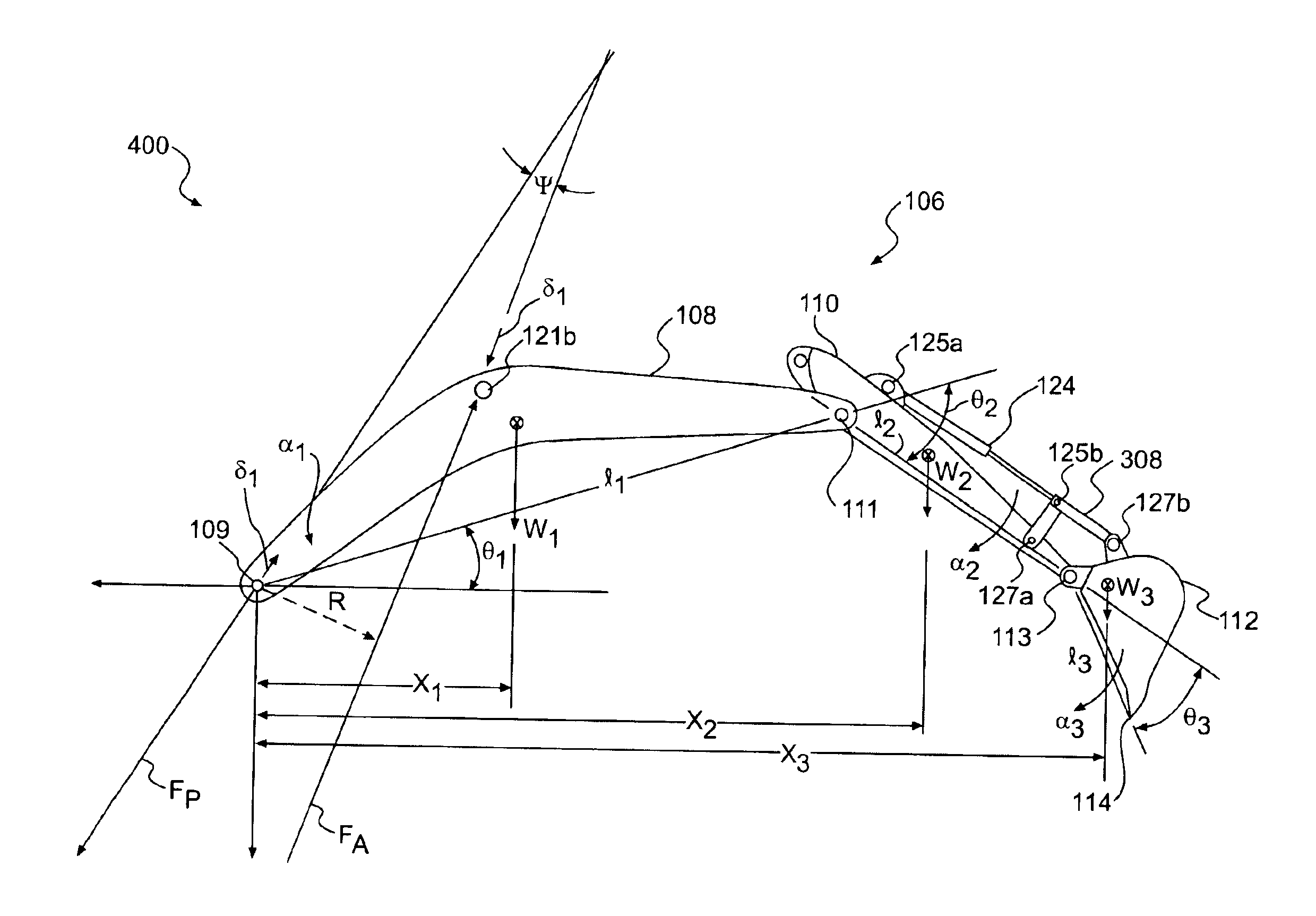
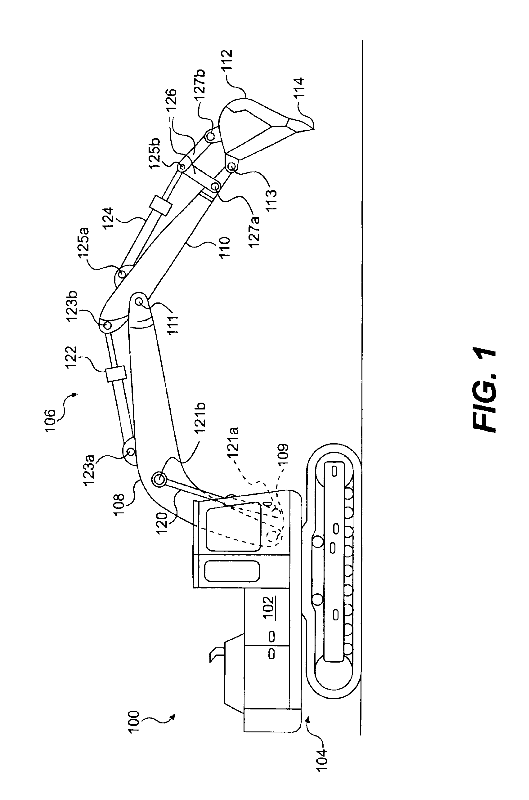
[0016]FIG. 1 shows a exemplary work machine 100 having a housing 102 mounted on an undercarriage 104. Although in this exemplary embodiment the work machine 100 is shown as an excavator, the work machine 100 could be a backhoe or any other work machine. The work machine 100 includes an implement arm 106 having mating components, such as, for example, a boom 108, a stick 110, and a work implement 112. The boom 108 may be connected to the housing 102 at a pinned boom joint 109 that allows the boom 108 to pivot about the boom joint 109. The stick 110 may be connected to the boom 108 at a pinned stick joint 111, and the work implement 112 may be connected to stick 110 the at a pinned work implement joint 113. The work implement 112 may include a work implement tip 114 at the distal-most end of the implement arm 106.

[0017]Movement of the implement arm 106 may be achieved by a series of cylinder actuators 120, 122 and 124 coupled to the implement arm 106 as is known in the art. For exampl...


PUM


Abstract

A control system for determining a position of an implement arm having a work implement is disclosed. The implement arm includes mating components connected by at least one joint. The control system includes at least one position sensor operably associated with the implement arm and configured to sense positional aspects of the implement arm. It also includes at least one load sensor operably associated with the implement arm, and configured to sense the direction of loads applied to the at least one joint. A controller is adapted to calculate a position of the implement arm based on signals received from the at least one position and load sensor. The calculated position takes into account shifting of the implement arm caused by clearances existing at the at least one joint between the mating components of the implement arm.

Description

[0001]This application is a continuation-in-part application of U.S. application Ser. No. 10 / 320,804, filed Dec. 17, 2002now U.S. Pat. No. 6,865,464, incorporated in its entirety herein by reference.TECHNICAL FIELD[0002]This invention relates to a system and method for accurately determining a position of an implement arm of a work machine. More specifically, this disclosure relates to a method and system for determining the position of a work implement of an implement arm of a work machine taking into account clearances existing between mating components of the implement arm.BACKGROUND[0003]Work machines, such as excavators, backhoes, and other digging machines, may include implement arms having a distally located work implement. The separate components making up the implement arm may be coupled by pin connections forming a series of implement arm joints. The pin connections are formed by positioning a pin within aligned holes in adjacent components of the implement arm. The pin co...

Claims


Application Information

Patent Timeline
IPC IPC(8): G06F7/00G06F19/00E02F3/43E02F9/20G16Z99/00
CPCE02F3/435E02F9/2025E02F9/264G16Z99/00
Inventor COLBURN, STEPHENPAWELSKI, PAUL C.
Owner CATERPILLAR INC
Learn More