System to optimize received power in an optical network

a technology of optical network and power level, applied in electromagnetic transmission, instruments, transmission, etc., can solve the problems of inability to maintain error-free signals, inability to optimize received power, and damage to the hardware of the receiver, so as to speed up installation and turn-up, optimize power levels, and simplify network installation and network upgrades

Inactive Publication Date: 2005-08-23
CIENA
View PDF2 Cites 19 Cited by
  • Summary
  • Abstract
  • Description
  • Claims
  • Application Information

AI Technical Summary

Benefits of technology

[0010]The system includes a graphical user interface (GUI) that guides an operator to determine optimal settings for a variable optical attenuator (VOA), thereby using the VOA to optimize the received power at a transceiver. The system simplifies network installation and network upgrades by not requiring a technician or operator to be physically present at e

Problems solved by technology

If the power is too high, then the transceiver hardware can be damaged, and/or errors may creep into the signals.
If the power is too low, then again, the signals may not remain error-free.
However, the process of installing pads is a labor-intensive procedure that involves the physical presence of personnel at each site.
During a network switching event, power

Method used


Image

  • System to optimize received power in an optical network
  • System to optimize received power in an optical network
  • System to optimize received power in an optical network

Examples


Embodiment Construction

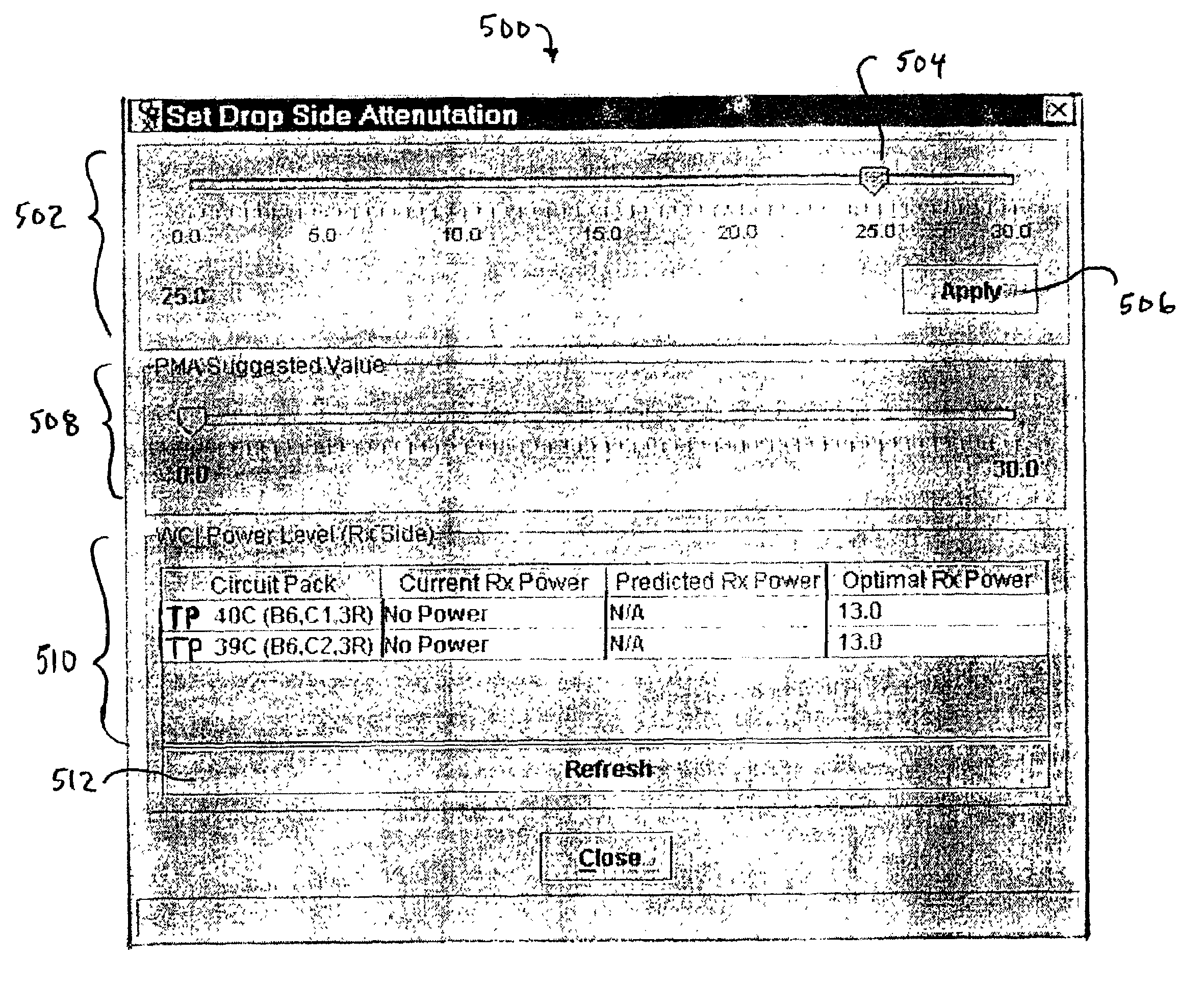
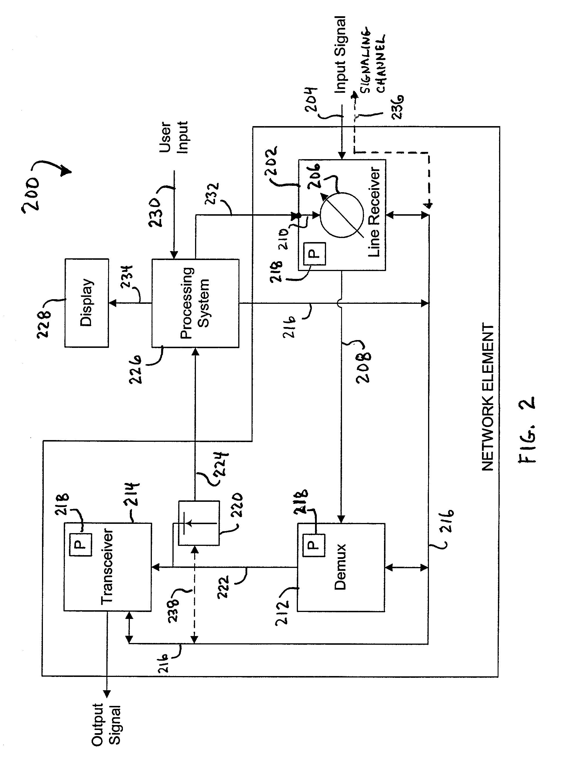
[0022]The present invention includes a system to optimize input power at an optical receiver in a network element (NE) that forms part of an optical network. In one embodiment, the system includes a graphical user interface to allow a network administrator or technician to determine and set optimal power levels at the input to a transceiver circuit card. The improved system results in highly accurate power settings that protect the cards from damage and provides cost savings, since it is not necessary to maintain and adjust individual pads. However, the invention is not limited to setting the power levels at only optical receiver circuit cards, and can be used to set input power levels at virtually any type of network card. Thus, various embodiments of the system included in the present invention are discussed in detail in the following text.

EXEMPLARY EMBODIMENT

[0023]In one embodiment included in the present invention, a system is provided that includes a graphical user interface (G...


PUM


Abstract

System to optimize received power at an input to a component in a network element that forms part of an optical network. The system includes a graphical user interface (GUI) that guides an installer to allow optimal setting for a variable optical attenuator (VOA) to be determined, thereby using the VOA to optimize the received power at the component. Power parameters are determined for each card in a signal path from the VOA to the input, and as part of the GUI, the system provides a display of calculated and received power to the user, thereby allowing the user to determine the optimal power setting.

Description

FIELD OF THE INVENTION[0001]The present invention relates generally to a system for controlling the power levels of signals in an optical network, and more particularly, to a system to optimize received power at an optical receiver in a network element.BACKGROUND OF THE INVENTION[0002]Optical networks are becoming widely used for distributing both high and low speed data over varying distances. Typically, an optical network is comprised of a number of network elements (NE) that are connected to each other in a variety of configurations so as to form a unified communication network. The communication network may extend over a small area, such as a company wide network, or may cover large distances, such as in regional or nationwide networks. Typically, the NE's allow network clients to input data for transmission over the network and to receive data transmitted over the network from other locations. Thus, data may be added or dropped from the network at NE locations as the data flows...

Claims


Application Information

Patent Timeline
IPC IPC(8): G06F15/00H04B10/158
CPCH04B10/66
Inventor VITTAL, CHIRADEEPGARG, GOPESH
Owner CIENA
Why Eureka
Try Eureka