Pilot valve

a pilot valve and valve body technology, applied in the field of pilot valves, can solve the problems of reducing the performance of the pilot valve, difficulty in providing such a seal, and leaking therefrom,

Inactive Publication Date: 2005-08-30
TECHNOLOG
View PDF19 Cites 19 Cited by
  • Summary
  • Abstract
  • Description
  • Claims
  • Application Information

AI Technical Summary

Benefits of technology

[0024]Preferably, the control chamber is at least partly bounded by a control chamber diaphragm in addition to the second chamber diaphragm. Preferably biassing means is located on the opposite side of the control chamber diaphragm to the control chamber. As will be explained i...

Problems solved by technology

However one disadvantage with the dual chamber pilot valves of FIGS. 2 and 3 is that in both cases a seal needs to be provided in order that the control fluid is prevented from entering the second part of the additional chamber i.e. that part of the chamber to which the control pressure is not applied.
The provision of such a seal can be difficult and deteriorati...

Method used


Image

  • Pilot valve
  • Pilot valve
  • Pilot valve

Examples


Embodiment Construction

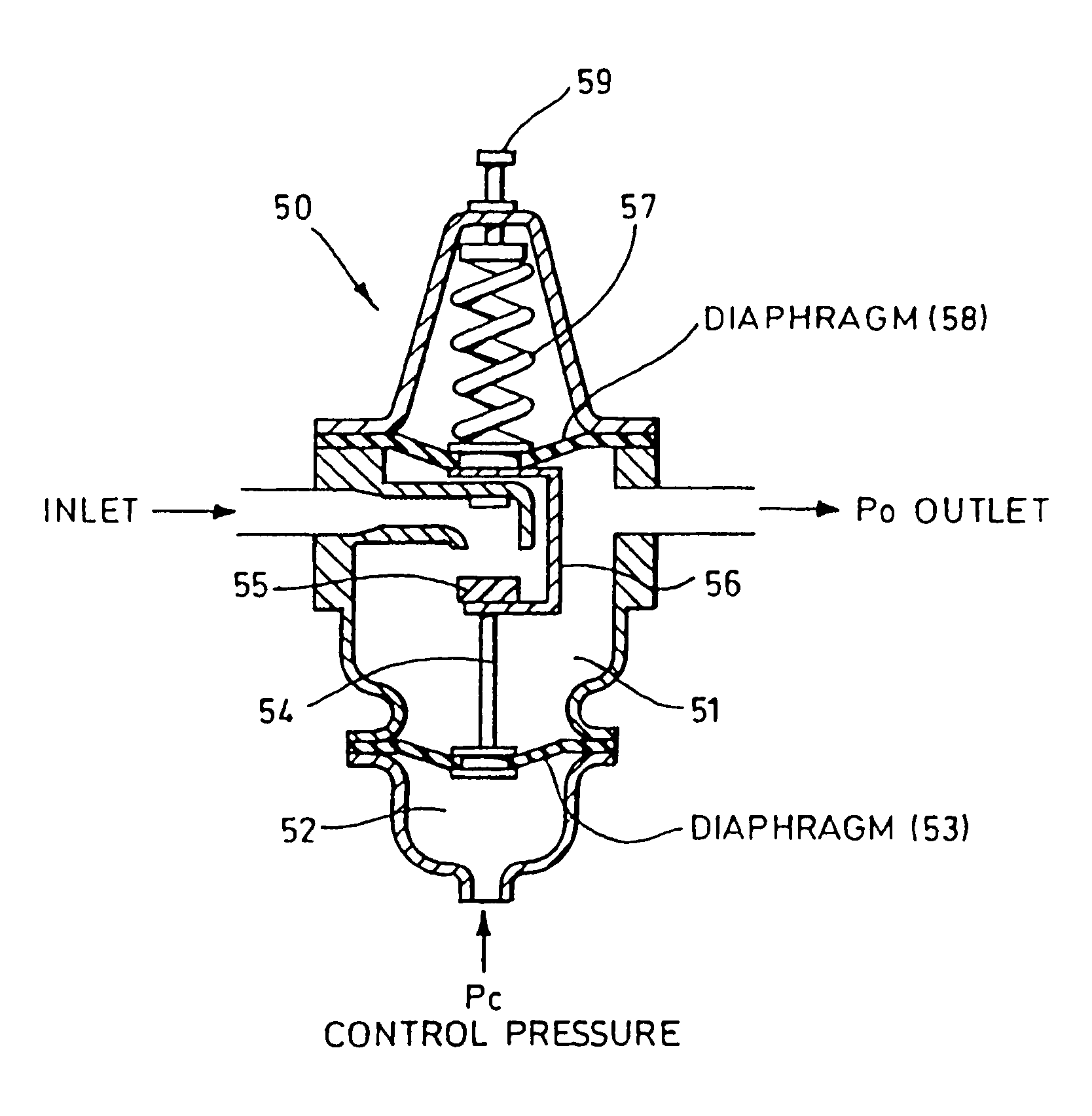
[0032]FIG. 5 shows a pilot valve 50 which includes a control chamber 51 and a second chamber 52. A control pressure Pc is applied to chamber 52 in use and chamber 52 is divided from control chamber 51 by a second chamber diaphragm 53.

[0033]The second chamber diaphragm 53 is rigidly connected via linkage 54 to a gate mechanism 55. The gate mechanism 55 is also connected via a further rigid linkage 56 to a spring 57. The spring 57 is isolated from the control chamber 51 by the control chamber diaphragm 58. The action of the force of the spring 57 on the diaphragm 58 may be adjusted by adjustment screw 59.

[0034]As can be seen from FIG. 5, the control fluid (which may be gas or water) present in the control chamber 51 acts against the opposite side of the second chamber diaphragm 53 to the control pressure Pc. In operation, if, for example, control pressure Pc is reduced then the gate 55 will open further causing the fluid flow through the control chamber to increase. When used in a PRV...


PUM


Abstract

There is provided a pilot valve (50), suitable for use in water and gas supply systems, the valve including biassing means (57), to control a gate (55), for controlling fluid flow through a control chamber (51), and a second chamber (52), which is sealed by a diaphragm (53), the second chamber (52), in use, receiving a control pressure for controlling the operation of the gate (55), such that an increase in control pressure acts to reduce fluid flow through the gate (55). The side of the diaphragm (53), against which the control pressure is not applied, is in fluid communication with the control chamber (51).

Description

CROSS-REFERENCE TO RELATED APPLICATION[0001]This application claims priority to PCT Application No. PCT / GB00 / 02127 filed 2 Jun. 2000, which claims priority to British Application No. 9913058.5 filed 4 Jun. 1999.BACKGROUND OF THE INVENTION[0002]The present invention relates to a pilot valve, for example of the type which is commonly used to control a pressure reducing valve in water and gas supply systems.[0003]FIG. 1 illustrates the use of a “single chamber” pilot valve 1 to control a pressure reducing valve (PRV—shown schematically as item 2) as commonly used in a water supply system. In the context of a gas supply system such a pressure reducing valve is normally known as a “regulator” or “governor”, but herein the single term “PRV” is used for simplicity as referring to both types of system. The fluid to be controlled (usually water or gas, and in this example will be taken to be water) flows along the main pipe 3 through the PRV. The outlet pressure (Po) is usually less than the...

Claims


Application Information

Patent Timeline
IPC IPC(8): G05D16/16G05D16/00
CPCG05D16/163Y10T137/7764Y10T137/7825Y10T137/7797
Inventor YONNET, CLAUDE
Owner TECHNOLOG
Why Eureka
Try Eureka