Plate dipole antenna

a dipole antenna and plate technology, applied in the field of dipole antennas, can solve the problems of increasing the gain of a dipole, less acceptability of a dipole, and not being able to use a dipole at all

Inactive Publication Date: 2005-08-30
AERIAL SCI
View PDF5 Cites 6 Cited by
  • Summary
  • Abstract
  • Description
  • Claims
  • Application Information

AI Technical Summary

Benefits of technology

[0005]It is the object of the present invention to go some way to alleviate the disadvantages described above, or at least provide the public with a useful choice.

Problems solved by technology

However, these dipoles perform less acceptably, if at all, for frequencies that are not harmonically related to the frequencies for which they are designed.
These dipoles are consequently unusable in some situations.
However known methods to increase the gain of a dipole reduce available bandwidth.
Low dipole gain and narrow dipole bandwidth lead to increases in the size of the resulting antenna assemblies.
Larger antennas use more materials and are more expensive to manufacture than smaller antennas.
They also have the disadvantages of taking more effort to secure and being more visually obtrusive.

Method used


Image

  • Plate dipole antenna
  • Plate dipole antenna
  • Plate dipole antenna

Examples


Embodiment Construction

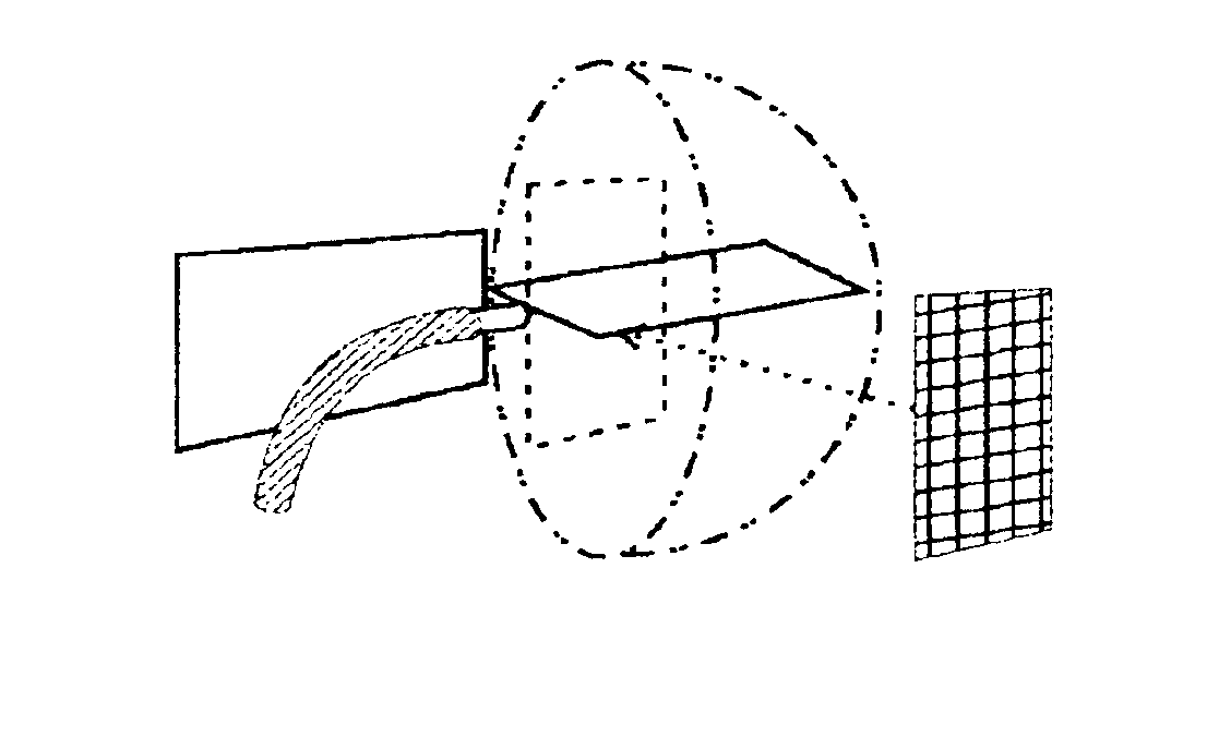
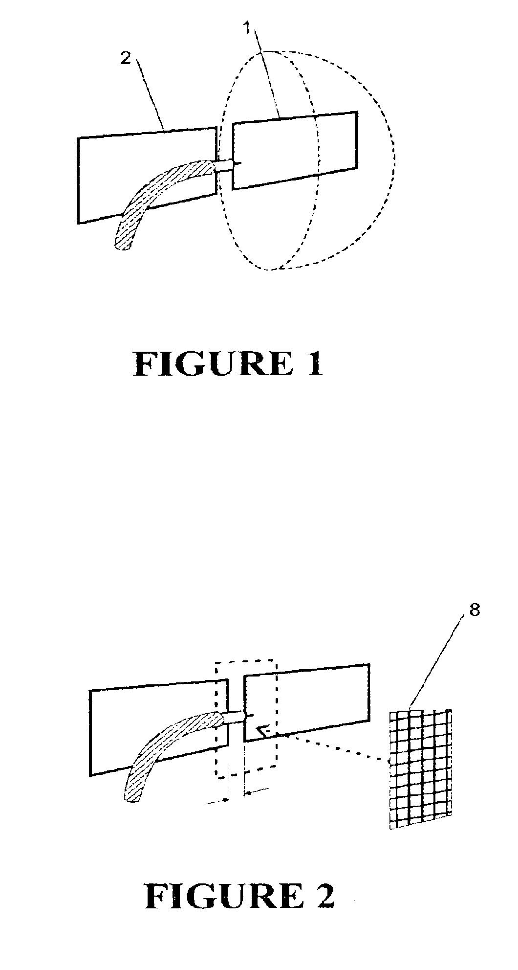
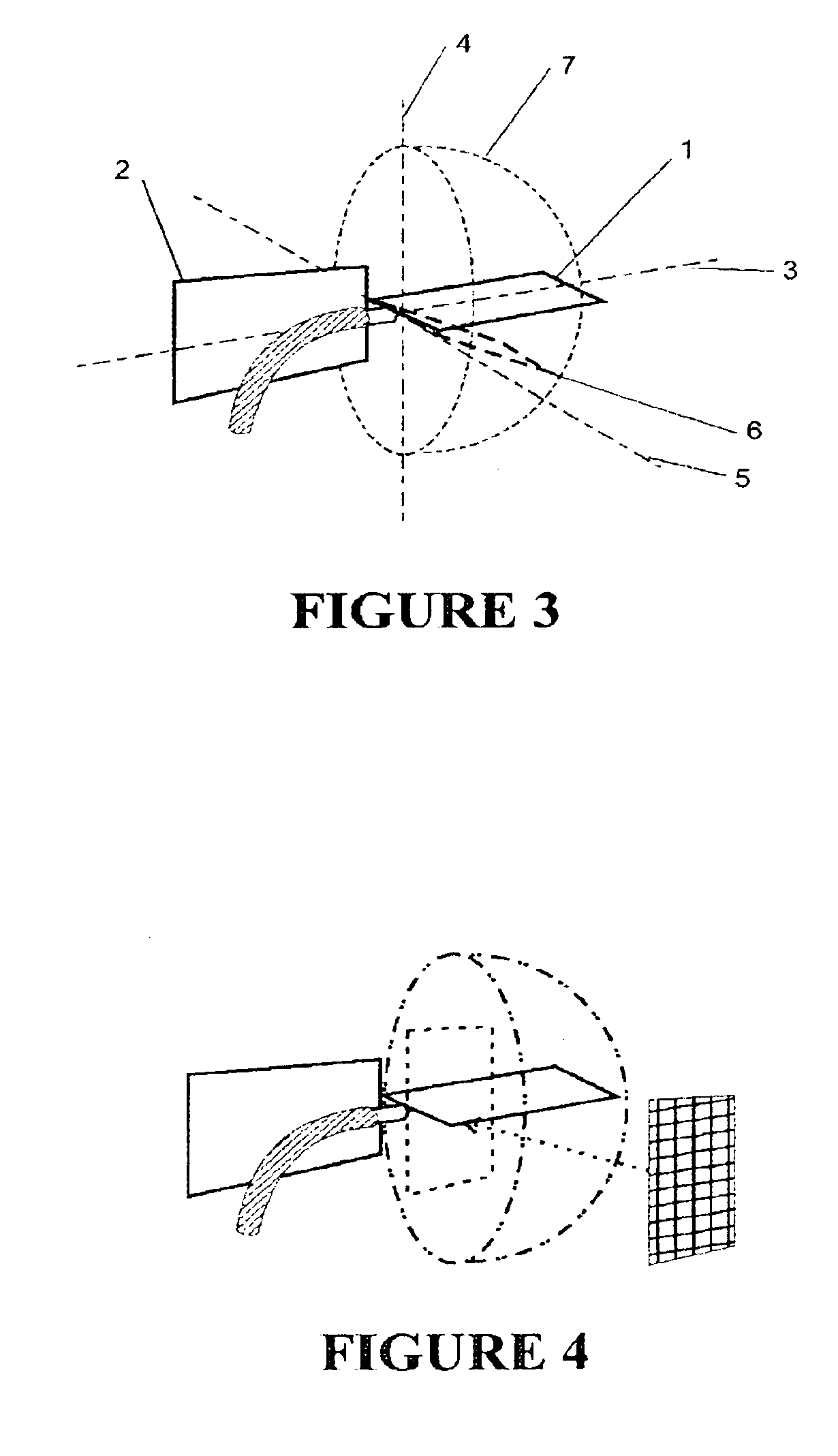
[0029]The antenna of FIG. 1 includes a pair of plates 1, 2 forming a dipole antenna. The plates are connected electrically or inductively to either a cable screen or a core. The plates of the antenna shown in FIG. 1 are rectangular but other shaped plates may be used within the definition of plate given above. The plates of the antenna of the invention are arranged in substantially the same plane.

[0030]As shown in FIG. 1 the plates of the antenna have a width to length ratio of greater than 1 to 10 where the longer plate dimension is the length and the shorter plate dimension is the width. Where the plate dimensions are not regular or other dipoles, skeletons etc have been attached to the plates, then different length and width measurements are used. If there are no additions to either plate of the pair then the length is the maximum length of the longest side of the plate and the width is the maximum width of the side of the plate perpendicular to the length. Should the plate lengt...


PUM


Abstract

A plate dipole antenna includes a pair of plates arranged in substantially the same plane or arranged in different planes, with a width to length ratio of one width unit to ten length units or greater. The plate dipole antenna may further include a gain plate.

Description

FIELD OF INVENTION[0001]The invention relates to dipole antennas and in particular to dipole antennas using plate elements.BACKGROUND[0002]For most known antenna designs the dipole elements are formed to specific lengths to resonate to specific frequencies. Dipoles are usually made up to suit 50 ohm, 75 ohm or 300 ohm impedances. Key measurements within the dipole are harmonics (eg 1, ½, ⅓, ¼) of specific frequency wavelength(s). A 50 ohm dipole is cut to a ¼ wave with an earth screen and a 75 ohm dipole is a balanced dipole made of two ¼ wave dipoles or a folded dipole with a balun. These dipoles are generally tubular. Such dipoles perform acceptably for frequencies close or harmonically related to the frequencies for which they are designed. However, these dipoles perform less acceptably, if at all, for frequencies that are not harmonically related to the frequencies for which they are designed.[0003]Known broadband dipole designs offer very low gain. These dipoles are consequentl...

Claims


Application Information

Patent Timeline
Patent Type & Authority Patents(United States)
IPC IPC(8): H01Q9/04H01Q9/28H01Q21/00
CPCH01Q9/285
Inventor HALL, GREGORY DANIEL
Owner AERIAL SCI
Why Eureka
Try Eureka