Insert module with permeable separation unit adapted for cooling requirement

a technology of insert modules and separation units, applied in the field of insert modules, can solve the problems of increasing the manufacturing cost of insert modules, and achieve the effects of reducing costs, simple mounting and dismounting, and simplifying the mounting of insert modules

Inactive Publication Date: 2005-08-30
AGILENT TECH INC
View PDF13 Cites 2 Cited by
  • Summary
  • Abstract
  • Description
  • Claims
  • Application Information

AI Technical Summary

Benefits of technology

[0007]By means of at least one permeable (preferably removable and / or exchangeable) separation unit, which is preferably provided by a separation wall, the housing is provided with a component area and a channel area. The permeability of the separation unit is preferably provided by a suitable porosity or perforation. As the component area serves for housing the electronic and / or optical components of the insert module, the channel area provides an inlet channel communicating with the housings entrance or an outlet channel communicating with the housings exit, respectively. In other words, an inlet channel or an outlet channel is integrated into the housing of the insert module according to the present invention. By use of different separation units the same housing can be adapted for varying equipment and / or for varying cooling requirements. To this aim, there only have to be provided different separation units, whereas the housings remain unchanged. Consequently, different insert modules need only one housing-type and thus materials management in the line of production of the insert modules can be simplified and therefore the manufacturing costs of the insert modules can be reduced.
[0009]To simplify the mounting of the insert module according to the invention, the separation unit is supported by a support comprising two longitudinal grooves, which face each other and in which the separation unit is inserted at its edges. In this embodiment the housing has an outer side wall adapted for providing a removable cap, whereby the removed cap provides an opening, through which the separation unit can be inserted into the grooves and be removed out of the grooves. The removable cap and the groove-support provide a simple mounting and dismounting of the separation unit and in particular allow a conversion of the respective insert module into another insert module with another measurement equipment having varying cooling requirements.
[0010]According to a preferred embodiment a portion of the housing comprises the channel area and a support adapted for supporting the separation unit, whereas said portion of the housing is formed in one piece. With help of this construction, the housing with the integrated channel or channel area, respectively, can be manufactured with reduced costs. To achieve comparatively small production costs, the one-piece portion of the housing may e.g. be provided by an extrusion molding process.

Problems solved by technology

These circumstances increase the manufacturing costs of the insert modules.

Method used


Image

  • Insert module with permeable separation unit adapted for cooling requirement
  • Insert module with permeable separation unit adapted for cooling requirement
  • Insert module with permeable separation unit adapted for cooling requirement

Examples


Embodiment Construction

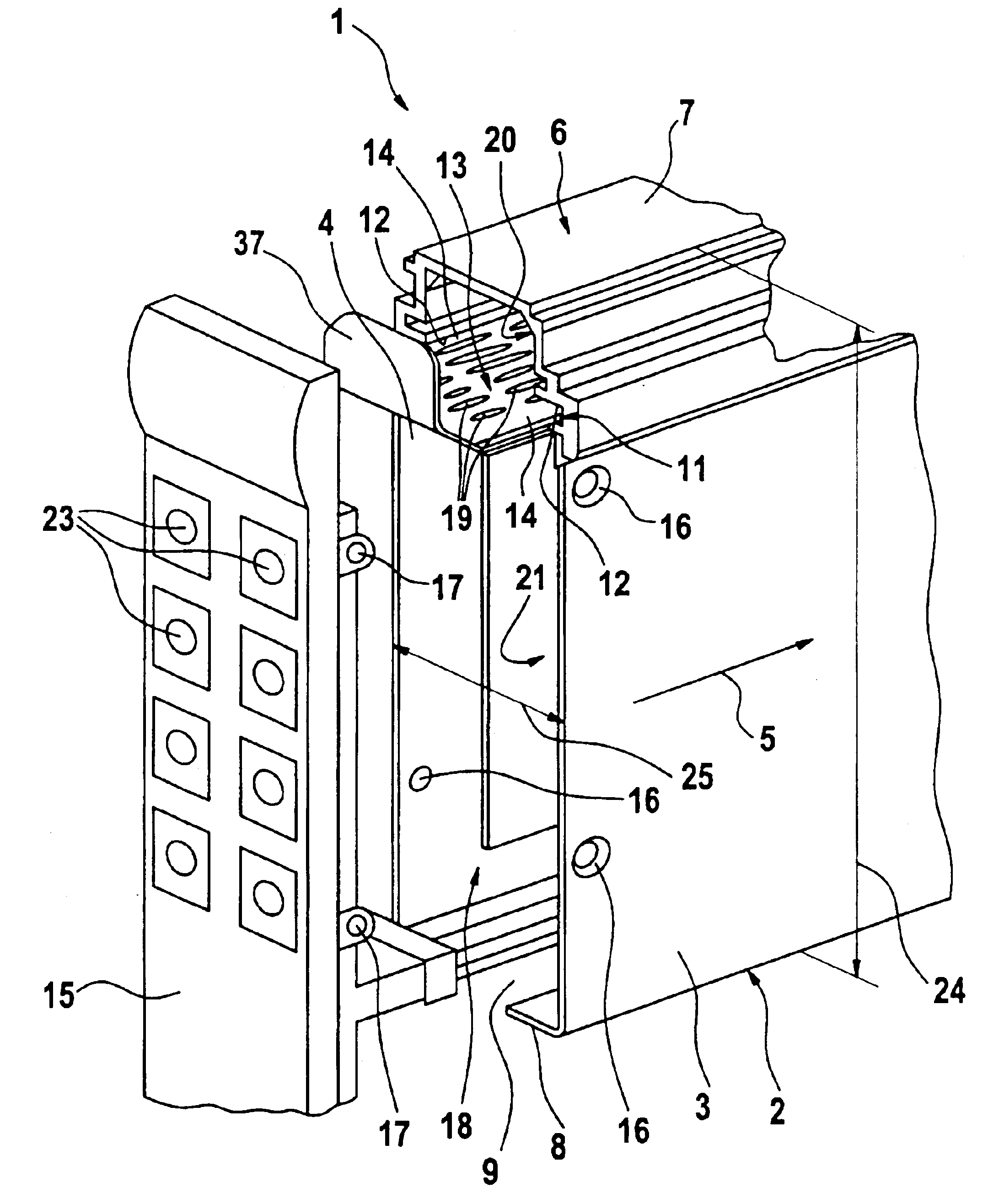
[0015]Referring to FIG. 1 an insert module 1 according to the present invention comprises a housing 2 with two parallel side walls 3 and 4 extending into a longitudinal direction of the housing 2. In FIG. 1 said longitudinal direction is symbolized by an arrow 5. The housing 2 comprises a portion 6, which forms or comprises in the shown example an upside 7 of the housing 2. The portion 6 is preferably made in one piece, e.g. by extrusion molding. At least one of the side walls 3, 4, here the side wall 4 turned away from the viewer, may be fabricated as an integral part of the one-piece portion 6. Therefore, the portion 6 comprises two adjacent side walls of the housing 2, namely said side wall 4 and the upside 7. Opposite to the upside 7 the housing 2 has an underside 8 comprising an opening 9. This opening 9 preferably provides an entrance of the housing 2, through which a cooling medium flow (in the FIGS. 2 to 4 designated with 10) may enter the housing 2. Apparently, the opening ...


PUM


Abstract

An insert module includes a housing having a component area for bearing one or more components, and a channel area communicating with at least one of an entrance and an exit of a cooling medium flow. The insert module provides at least a part of a flow path of the cooling medium flow, where the cooling medium enters the insert module through the entrance, flows at least partly through the insert module at least partly passing the component area, and at least partly exits the insert module through the exit. At least one permeable separation unit is adapted for separating the component area from the channel area and includes at least one permeable and at least one impermeable portion. An allocation of the at least one permeable and the at least one impermeable portion is adapted to the cooling requirements of the components arranged within the component area.

Description

BACKGROUND OF THE INVENTION[0001]The present invention relates to an insert module adapted for inserting into a device, wherein said device is adapted for receiving or generating a cooling medium flow, e.g. from or by means of a fan or blower.[0002]Such insert module normally comprises a housing, in which electronic and / or optical components like e.g. measurement equipment, computer, semiconductors, microprocessors, memory are arranged. During operation, the components of the insert module usually generate heat, which has to be transported out of the housing to prevent the components from overheating. To this aim the housing comprises an entrance and an exit for the cooling gas flow of the measurement device. When the insert module is inserted into the housing, the insert module is integrated into a flow path of the cooling gas flow. During operation of the measurement device, the cooling gas flow enters the inserted insert module through the entrance, then flows through the insert ...

Claims


Application Information

Patent Timeline
Patent Type & Authority Patents(United States)
IPC IPC(8): H05K7/20G06F1/20
CPCH05K7/20563
Inventor MUENNICH, CHRISTIAN
Owner AGILENT TECH INC
Why Eureka
Try Eureka