Short wire length wire-winding box

Inactive Publication Date: 2005-08-30
LIAO SHENG HSIN
View PDF9 Cites 83 Cited by
  • Summary
  • Abstract
  • Description
  • Claims
  • Application Information

AI Technical Summary

Benefits of technology

[0008]Accordingly, the primary object of the present invention is to provide an improved short wire length wire-winding box, wherein a communication wire is wound around a pivotal shaft (inner circle) first and then around a second ring (outer circle) in the same direction. When the communication wire is directly pulled out from the wire-windi

Problems solved by technology

However, because there are so many components of these conductive rings and conductive resilient leaves or steel balls, and each component has a very small volume, the assembly is time-consuming and difficult.
Moreover, bad contact or other failures may easily a

Method used


Image

  • Short wire length wire-winding box
  • Short wire length wire-winding box
  • Short wire length wire-winding box

Examples


second embodiment

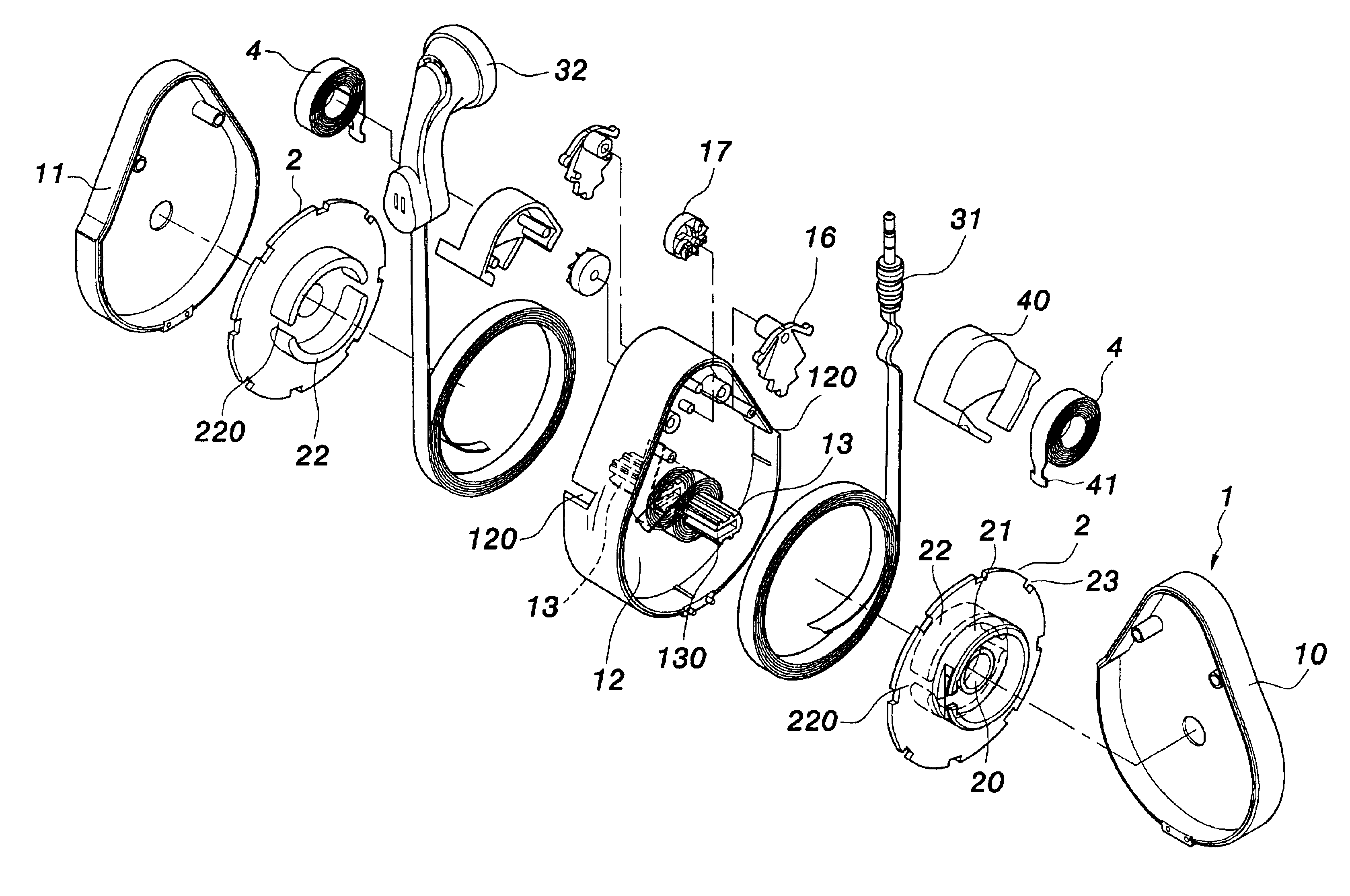
[0038]Furthermore, referring to FIG. 9, the present invention is illustrated. In this embodiment, the pivotal-shaft 13 in the receiving groove 12 is separated. That is, the pivotal shaft 13 and the receiving groove 12 of the casing 1 are separate. One end of the pivotal shaft 13 is connected to a buckling body 131. A corresponding buckling groove 111 is installed in the receiving groove 12 of the casing 1. The buckling body 131 and the buckling groove 111 are engaged so that the pivotal shaft 13 can be assembled to the receiving groove 12 of the casing 1. Since the pivotal shaft 13 is separable, the communication wire 3 can be wound around the pivotal shaft 13 firstly at the outer side of the casing 1, and the pivotal shaft 13 is then assembled to the receiving groove 12 of the casing 1, thereby achieving easy and convenient winding operation.

third embodiment

[0039]Moreover, with reference to FIG. 10, the present invention is illustrated. In this embodiment, the casing 1 is formed by assembling a first casing half 10, a second casing half 11 and a middle seat 18 with two receiving grooves 12 formed therein. The two receiving grooves 12 are arranged at two surfaces of the middle seat 18. Each receiving groove 12 is installed with a pivotal shaft 13. Each pivotal shaft 13 is installed with a wire outlet 130. The two wire outlets 130 are communicated with one another. The lateral side of the casing 1 is installed with two wire outlets 120. Furthermore, two rotary disks 2 and two spiral reeds 4 are installed in the two receiving grooves 12, respectively. The communication wire 3 is installed in the two receiving grooves 12. The middle part of the communication wire 3 is installed at the two wire outlets 130 of the two pivotal shafts 13. Two wire ends of the communication wire 3 are wound around the two pivotal shafts 13 for several turns, pa...

fourth embodiment

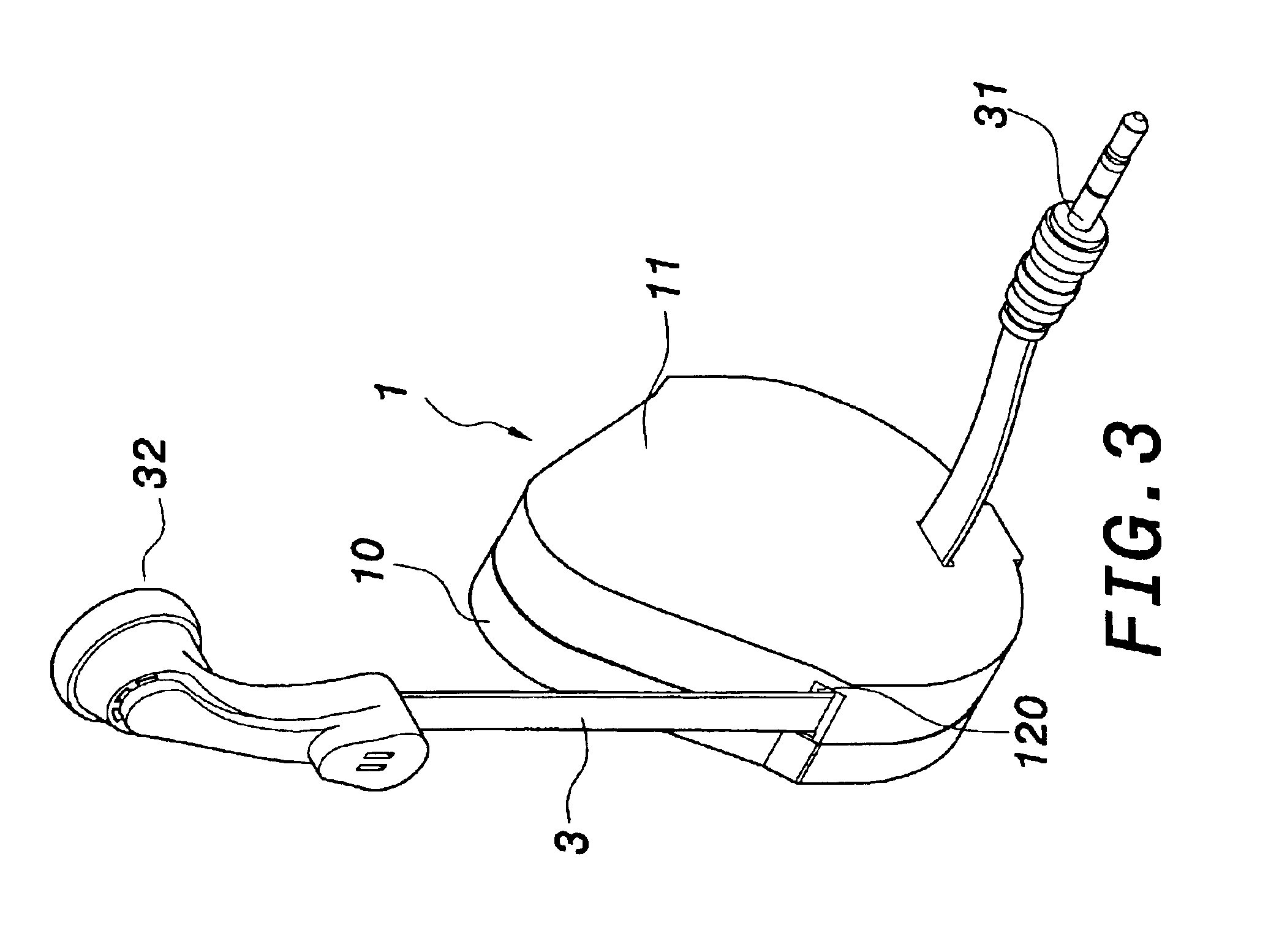
[0040]Additionally, referring to FIGS. 11 and 12, the present invention is illustrated. In this embodiment, two wire-winding boxes are connected together. An earphone 33 is disposed in each of the two wire-winding boxes. A corresponding audio hole 19 is disposed on the casing 1 of each of the two wire-winding boxes. The two wire-winding boxes are connected together via a communication wire 3. One wire end of one communication wire 3 of one of the two wire-winding boxes is assembled to an audio source plug 34. An ear hanger 101 is disposed on the casing 1 of each of the two wire-winding boxes to be hung on the ear of a user. Moreover, the shape of the ear hanger 101 can be changed (referring to FIG. 13).


PUM


Abstract

An improved short wire length wire-winding box includes a rotary disk driven by a spiral reed and pivotally installed in a casing having a receiving groove. The communication wire is at first wound around a pivotal shaft (inner circle) for several turns, and then is placed in the rotary disk. The rotary disk is rotated so that the communication wire is wound around a second ring (outer circle) in the same direction. When the communication wire is directly pulled out from the wire-winding box, the communication wire wound around the pivotal shaft will be pulled more and more tightly so that the communication wire wound around the pivotal shaft will not disperse for avoiding the situation that part of the communication wire can not be rewound. Moreover, the communication wire wound around the pivotal shaft can be tightly positioned thereon without any positioning device.

Description

FIELD OF THE INVENTION[0001]The present invention relates to an improved short wire length wire-winding box and, more particularly, to an improved short wire length wire-winding box applicable to short-distance wired communication apparatuses, whereby a communication wire of required length can be pulled out freely and can also be automatically rewound timely.BACKGROUND OF THE INVENTION[0002]Appropriate communication wires need to be accommodated to achieve electrical connection when using communications apparatuses such as computers, modems, telephones, or facsimile apparatuses. To avoid entanglement of wire due to a too-long length of external wire or inconvenience of use due to a too-short length of external wire, several kinds of wire-winding boxes applicable to various kinds of communications apparatuses have been proposed. A general conventional wire-winding box comprises a casing, a rotary disk, a spiral reed, and a communication wire. The spiral reed and the rotary disk are ...

Claims


Application Information

Patent Timeline
IPC IPC(8): B65H75/40B65H75/38B65H75/44H02G11/02H02G11/00H04M1/04H04M1/05H04M1/15
CPCB65H75/4434B65H75/4449H02G11/02H04M1/05H04M1/15
Inventor LIAO, SHENG HSIN
Owner LIAO SHENG HSIN
Why Eureka
Try Eureka