
Hunter concealment system

a concealment system and hunter technology, applied in protective equipment, building types, construction, etc., can solve the problems of requiring a significant amount of effort to remove, affecting the hunter, and time not automatically opening, etc., and achieve the effect of con

Inactive Publication Date: 2005-09-06
PHOENIX RUBBER GUMIIPARI
View PDF18 Cites 4 Cited by
  • Summary
  • Abstract
  • Description
  • Claims
  • Application Information

AI Technical Summary

Benefits of technology

[0011]In view of the foregoing disadvantages inherent in the known types of camouflage devices now present in the prior art, the present invention provides a new hunter concealment system construction wherein the same can be utilized for effectively concealing a hunter without physically interfering with the hunter.
[0017]A second object is to provide a hunter concealment system for effectively concealing a hunter without physically interfering with the hunter.
[0020]An additional object is to provide a hunter concealment system that is low profile.
[0021]A further object is to provide a hunter concealment system that does not require significant effort to engage or disengage.
[0022]Another object is to provide a hunter concealment system that is lightweight and easy to transport.
[0023]A further object is to provide a hunter concealment system that allows for the interchanging of camouflage patterns.

Problems solved by technology

The main problem with conventional camouflage devices is that they require a significant amount of effort to remove before attempting to shoot a gun.
Another problem with conventional camouflage devices is that they sometimes interfere with the hunter while the hunter attempts to fire the gun.
Another problem with conventional camouflage devices is that they often times do not automatically open for the hunter to be freely exposed.
While these devices may be suitable for the particular purpose to which they address, they are not as suitable for effectively concealing a hunter without physically interfering with the hunter.
Conventional camouflage devices do not provide an effective system for camouflaging a hunter and allowing the hunter to easily fire a gun.

Method used


Image

  • Hunter concealment system
  • Hunter concealment system
  • Hunter concealment system

Examples


Embodiment Construction

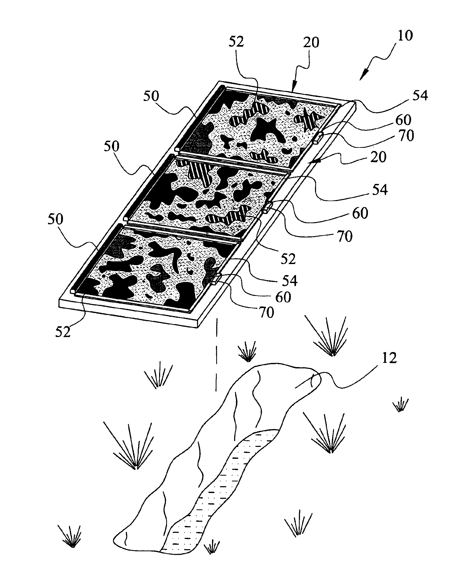
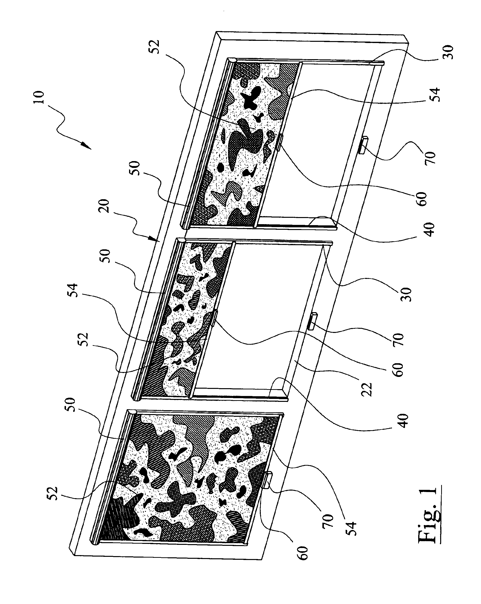
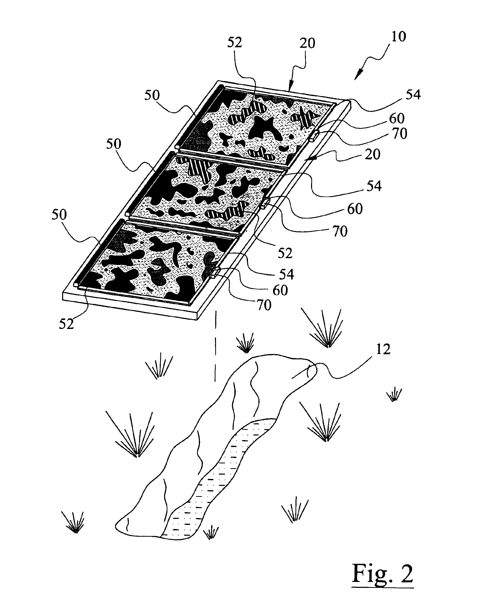
[0033]Turning now descriptively to the drawings, in which similar reference characters denote similar elements throughout the several views, FIGS. 1 through 6 illustrate a hunter concealment system 10, which comprises a frame structure 20 having at least one opening 22, a first rail 30 and a second rail 40 on opposing sides of each opening, a recoil unit 50 attached to an end of each opening, a camouflage sheet 52 retained within the recoil unit 50, a first connector 60 attached to a handle member 54 of the camouflage sheet 52, and a second connector 70 attached to the frame for catchably receiving the first connector 60. The hunter concealment system is positioned over a goose pit 12 or other location for the purpose of selectively concealing the hunter. When the hunter desires, they simply engage the handle member 54 thereby releasing the first connector 60 which allows the recoil unit 50 to automatically draw the camouflage sheet 52 into the recoil unit 50.

[0034]FIG. 1 best illus...


PUM


Abstract

A hunter concealment system for effectively concealing a hunter without physically interfering with the hunter. The hunter concealment system includes a frame structure having a plurality of openings, a first rail and a second rail on opposing sides of each opening, a recoil unit attached to an end of each opening, a camouflage sheet retained within the recoil unit, a first connector attached to a handle member of the camouflage sheet, and a second connector attached to the frame for catchably receiving the first connector. The hunter concealment system is positioned over a goose pit or other location for the purpose of selectively concealing the hunter. When the hunter desires, they simply engage the handle member thereby releasing the first connector which allows the recoil unit to automatically draw the camouflage sheet into the recoil unit.

Description

CROSS REFERENCE TO RELATED APPLICATIONS[0001]Not applicable to this application.STATEMENT REGARDING FEDERALLY SPONSORED RESEARCH OR DEVELOPMENT[0002]Not applicable to this application.BACKGROUND OF THE INVENTION[0003]1. Field of the Invention[0004]The present invention relates generally to hunter camouflage devices and more specifically it relates to a hunter concealment system for effectively concealing a hunter without physically interfering with the hunter.[0005]2. Description of the Related Art[0006]Hunter camouflage devices have been in use for years. Conventional camouflage devices have various forms and structures such as but not limited clothing, sheet material, partial enclosures and full enclosures.[0007]The main problem with conventional camouflage devices is that they require a significant amount of effort to remove before attempting to shoot a gun. Another problem with conventional camouflage devices is that they sometimes interfere with the hunter while the hunter atte...

Claims


Application Information

Patent Timeline
IPC IPC(8): E04H15/00
CPCE04H15/001F41H3/00Y10S135/901Y10S135/903
Inventor COURSEY, BRADLEY W.
Owner PHOENIX RUBBER GUMIIPARI
Learn More