Radiator

a radiationator and heat dissipation technology, applied in the field of radiationators, can solve the problems of lower heat dissipation efficiency, and achieve the effect of preventing excessive heat dissipation efficiency of electronic devices and balancing pressur

Active Publication Date: 2005-09-06
INVENTEC CORP
View PDF5 Cites 26 Cited by
  • Summary
  • Abstract
  • Description
  • Claims
  • Application Information

AI Technical Summary

Benefits of technology

[0005]The primary object of the invention is to provide a radiator adopted for use on electronic devices that have radiator fans installed in series and allows air inside the electronic device to flow outwards in the positive direction in case any of the radiator fans stops operation. Thereby, to balance pressure and prevent the heat dissipation efficiency of the electronic device from dropping excessively.
[0006]The radiator according to the invention includes a case, radiator fans installed in series and a membrane check valve. The membrane check valve includes a frame, a bracing bracket and membrane petals. The bracing bracket is located in the frame to form a plurality of cells with the frame. The membrane petals have one end attached to one side of the frame. When air flows in the positive direction through the cells to the membrane petals, the membrane petals move away from the bracing bracket. When the air flows in the reverse direction to the membrane petals, the membrane petals attach to the bracing bracket. Thus when the radiator of the invention is adopted on an electronic device, air inside the electronic device can flow outwards in the positive direction when any of the radiator fans stops operation. Thereby, the pressure may be balanced and heat dissipation efficiency may be prevented from dropping excessively.
[0007]Through installing the membrane check valve between the radiator fan and the inner wall surface of the case, and completely covering the surrounding of the radiator fans, and with the membrane petals being more directed towards air outlets of the radiator fans than the bracing bracket, air inside the electronic device can flow outwards in the positive direction when any of the radiator fans stops operation. Thereby, pressure may be balanced and heat dissipation efficiency of the electronic device may be prevented from dropping excessively. Of course the membrane check valve does not have to cover the surrounding of the radiator fan completely to achieve the same result.
[0008]By means of the construction set forth above, when the electronic device has two or more radiator fans installed in series and any one of the radiator fans stops operation, the membrane check valve of the invention can prevent heat dissipation efficiency of the electronic device from dropping excessively.

Problems solved by technology

However, if any one of the radiator fans stops operation, the resulting heat dissipation efficiency is lower than only one radiator fan is installed.

Method used


Image

  • Radiator
  • Radiator
  • Radiator

Examples


Embodiment Construction

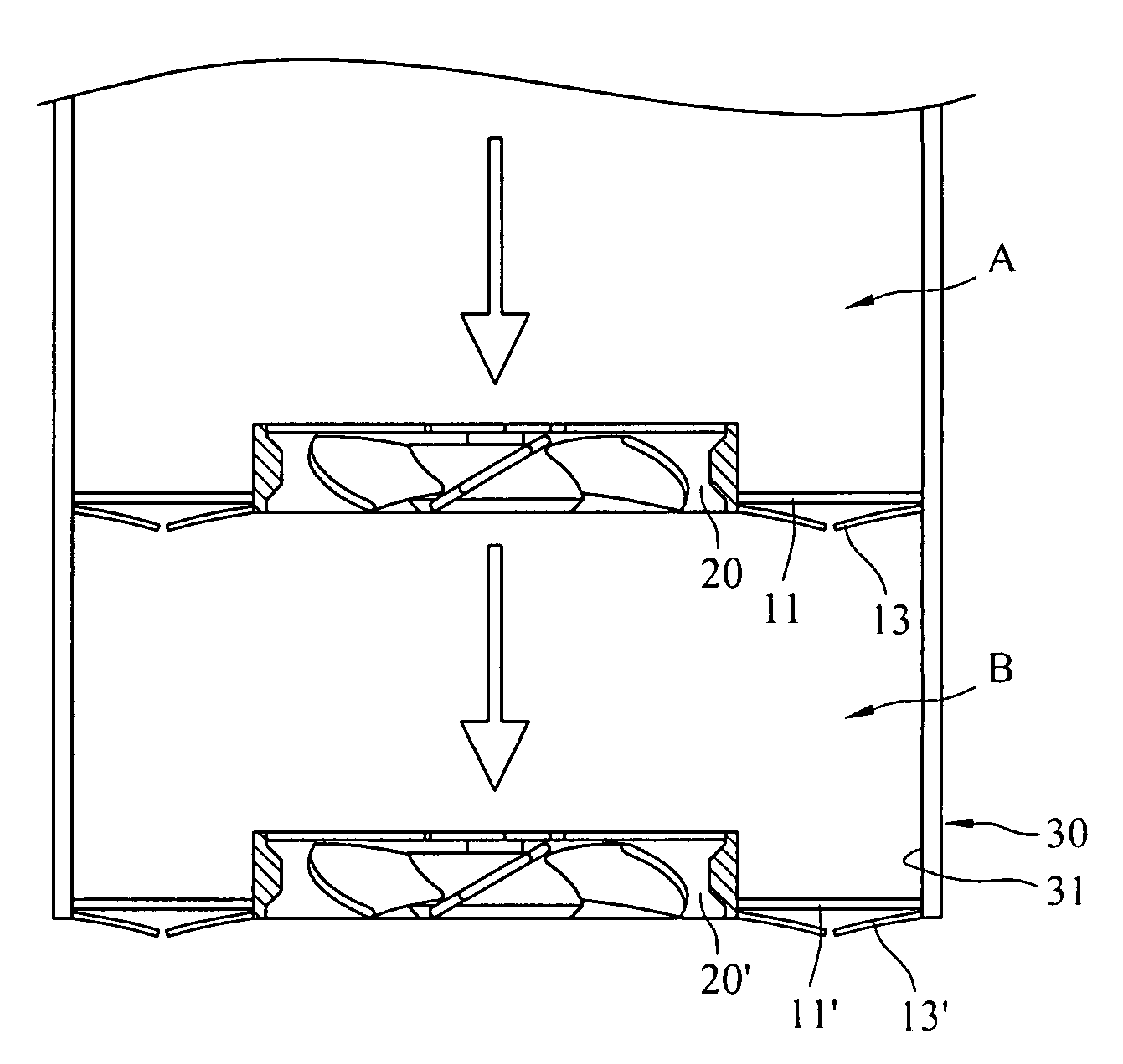
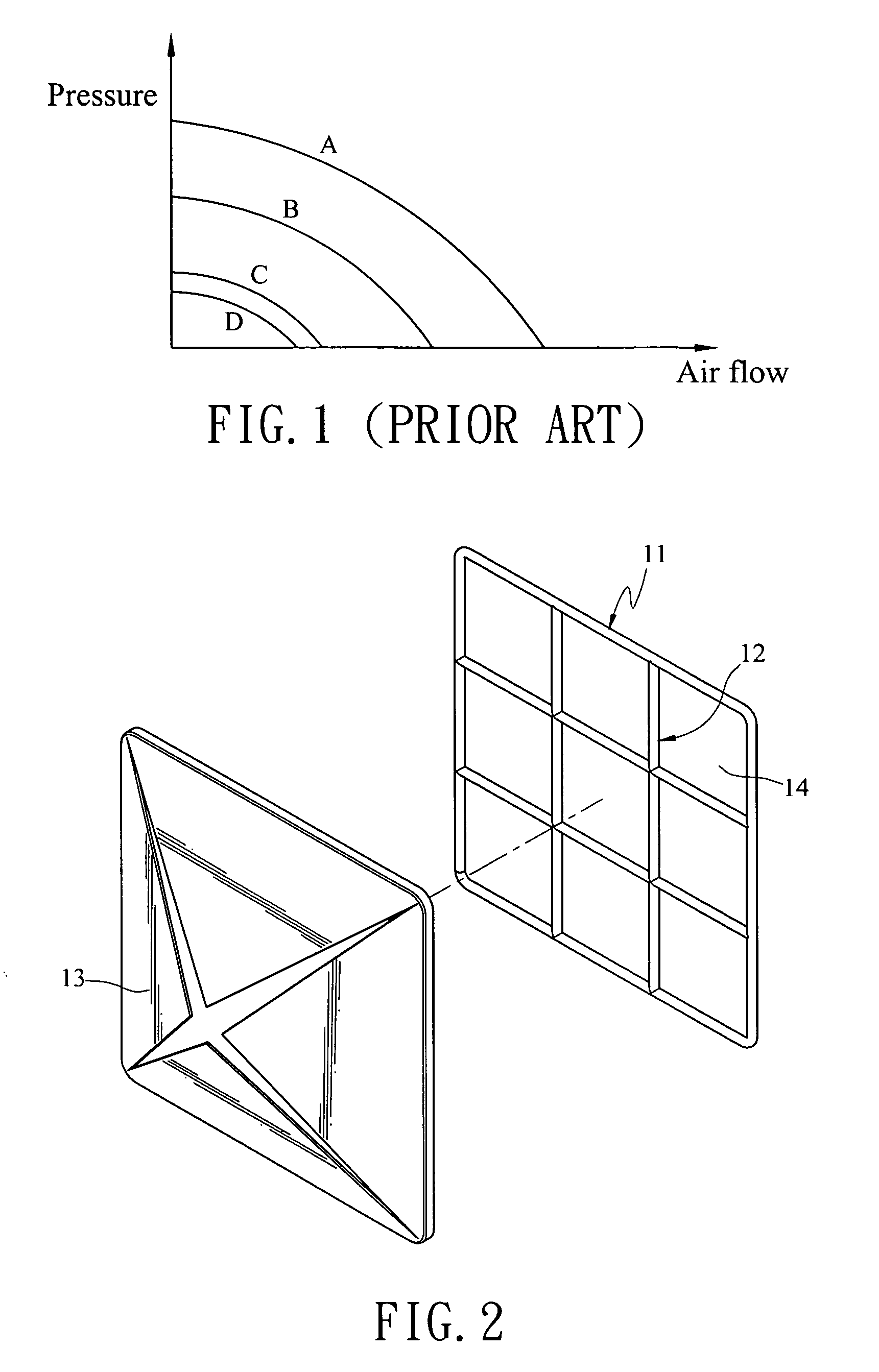
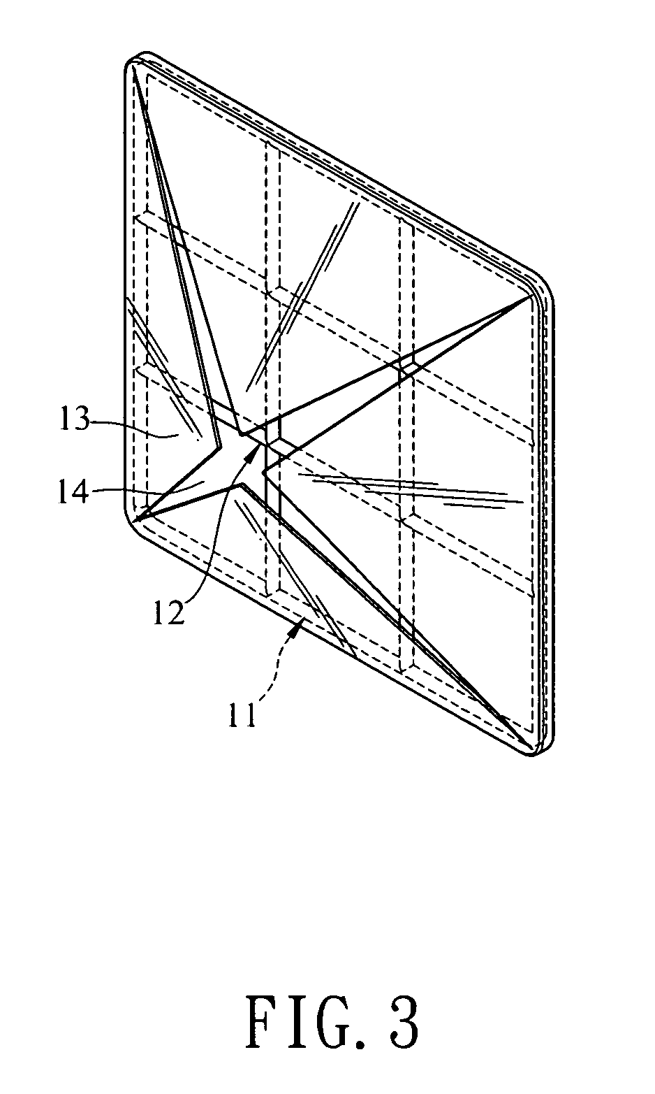
[0017]Referring to FIGS. 5 through 6C, the radiator according to the invention includes a case 30, radiator fans 20 and 20′ arranged in series and a membrane check valve. Also referring to FIGS. 2 through 4B, the membrane check valve includes a frame 11 (11′), a bracing bracket 12 (12′) and membrane petals 13 (13′). The bracing bracket 12 (12′) is located in the frame 11 (11′) to form a plurality of cells 14 (14′). The membrane petals 13 (13′) have one end attaching to one side of the frame 11 (11′). When air flows in the positive direction through the cells 14 (14′) to the membrane petals 13 (13′), the membrane petals 13 (13′) move away from the bracing bracket 12 (12′). When the air flows in the reverse direction towards the membrane petals 13 (13′), the membrane petals 13 (13′) attach to the bracing bracket 12 (12′). Thus when the radiator of the invention is adopted on an electronic device with the radiator fans 20 and 20′ installed in series (referring to FIGS. 6A, 6B and 6C), ...


PUM


Abstract

A radiator, adopted on electronic devices with radiator fans installed in series, includes a case, two or more radiator fans and a membrane check valve. The radiator fans are located on the inner wall surface of the case. The membrane check valve has a frame, at least one bracing bracket and membrane petals. The frame is located between the radiator fan and the inner wall surface of the case. The bracing bracket is located in the frame to form a plurality of cells with the frame. The membrane petals' one end attaches to one side of the frame and is more directed towards air outlets of the radiator fans than the bracing bracket. When any radiator fans stops operation, air inside the electronic devices flow outwards in the positive direction to balance the pressure and prevent heat dissipation efficiency of the electronic devices from dropping excessively.

Description

FIELD OF THE INVENTION[0001]The invention relates to a radiator adopted for use on electronic devices that have radiator fans installed in series and particularly to a radiator that allows air inside an electronic device to flow outwards in the positive direction to balance the pressure without excessively reducing heat dissipation efficiency when any of the radiator fans stops operation.BACKGROUND OF THE INVENTION[0002]Nowadays electronic devices have almost become necessary goods in people's life. When the electronic device is in use, heat energy is generated. Hence the electronic device usually has radiator fans. The radiator fan has rotary vanes to discharge heated air and maintain the electronic device at a desired temperature for normal operation. For more delicate electronic devices, a great amount of heat energy is generated. Hence increasing heat dissipation efficiency of the electronic device is important.[0003]Referring to FIG. 1 for a chart showing the relationship betwe...

Claims


Application Information

Patent Timeline
Patent Type & Authority Patents(United States)
IPC IPC(8): F24H3/02F28F1/00H05K7/20
CPCH05K7/20172
Inventor LIN, SHU-JU
Owner INVENTEC CORP
Why Eureka
Try Eureka