Pipe running tool

a running tool and pipe technology, applied in the direction of drilling pipes, drilling holes/well accessories, rotary drilling, etc., can solve the problems of system failure, method is relatively labor-intensive and therefore costly, and cumbersome and relatively inefficien

Inactive Publication Date: 2005-09-06
VARCO INT INC
View PDF31 Cites 49 Cited by
  • Summary
  • Abstract
  • Description
  • Claims
  • Application Information

AI Technical Summary

Benefits of technology

[0012]In another illustrative embodiment, the present invention is directed to a method of assembling a pipe string, including the steps of: actuating a lower pipe engagement assembly to releasably engage a pipe segment; lowering a top drive assembly to bring the pipe segment into contact with a pipe string; monitoring t

Problems solved by technology

The conventional manner in which plural casing segments are coupled together to form a casing string is a labor-intensive method involving the use of a “stabber” and casing tongs.
While such a method is effective, it is cumbersome and relatively inefficient because the procedure is done manually.
Thus, such a method is relatively labor-intensive and therefore costly.
Furthermore, using casing tongs requires the setting up of scaffolding or other like structures, and is therefore inefficient.
While such a system provides benefits over the more con

Method used


Image

  • Pipe running tool
  • Pipe running tool
  • Pipe running tool

Examples


Embodiment Construction

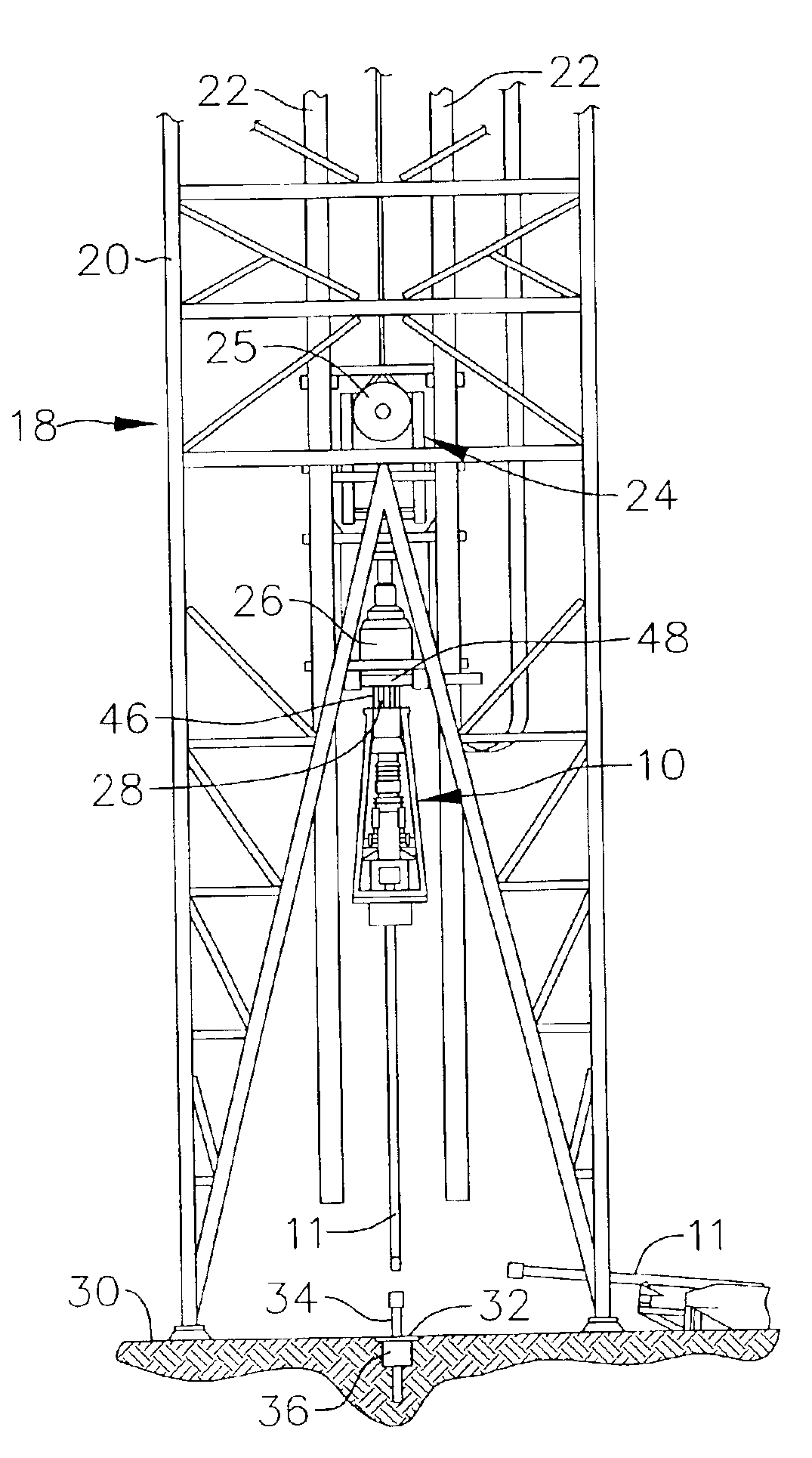
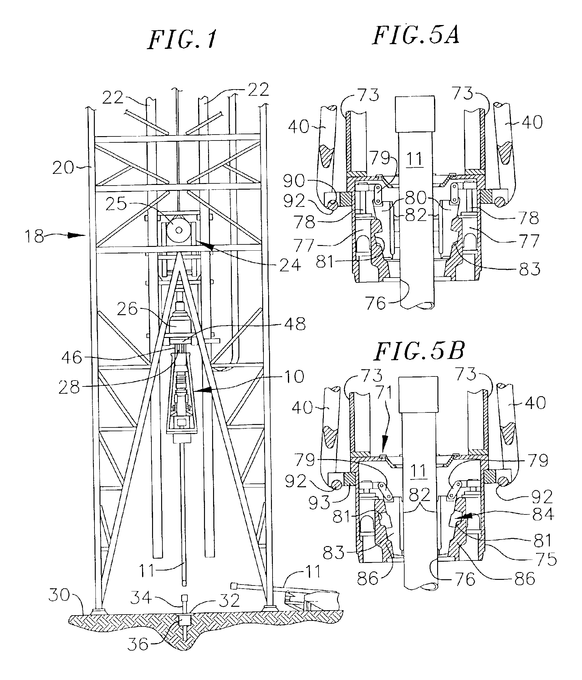
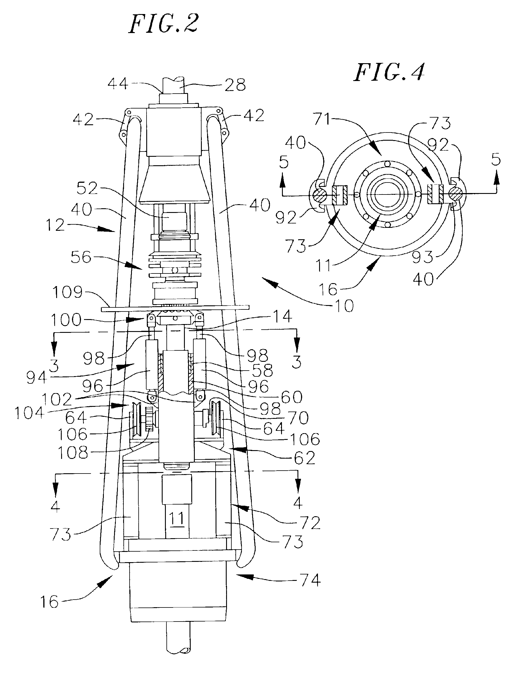
[0022]In the following detailed description, like reference numerals will be used to refer to like or corresponding elements in the different figures of the drawings. Referring now to FIGS. 1 and 2, there is shown a pipe running tool 10 depicting one illustrative embodiment of the present invention, which is designed for use in assembling pipe strings, such as drill strings, casing strings, and the like. The pipe running tool 10 comprises, generally, a frame assembly 12, a rotatable shaft 14, and a lower pipe engagement assembly 16 that is coupled to the rotatable shaft for rotation therewith. The pipe engagement assembly is designed for selective engagement of a pipe segment 11 (FIGS. 1, 2, and 5A) to substantially prevent relative rotation between the pipe segment and the pipe engagement assembly. The rotatable shaft 14 is designed for coupling with a top drive output shaft from an existing top drive, such that the top drive, which is normally used to rotate a drill string to dril...


PUM


Abstract

A pipe running tool for use in an oil drilling system and the like comprises a lower drive shaft adapted to engage a drive shaft of a top drive assembly for rotation therewith. The pipe running tool further includes a lower pipe engagement assembly which is driven to rotate by the lower drive shaft, and is designed to releasably engage a pipe segment in such a manner to substantially prevent relative rotation between the two. Thus, when the lower pipe engagement assembly is actuated to securely hold a pipe segment, the top drive assembly may be actuated to rotate the top drive output shaft, which causes the lower drive shaft and lower pipe engagement assembly to rotate, which in turn rotates the pipe segment.

Description

CROSS-REFERENCE TO RELATED APPLICATION(S)[0001]This application is a continuation of U.S. patent application Ser. No. 09 / 518,122, filed Mar. 3, 2000, now U.S. Patent No. 6,443,241, which claims priority under 35 U.S.C. § 119(e) to U.S. Provisional Patent Application No. 60 / 122,915 filed Mar. 5, 1999.BACKGROUND OF THE INVENTION[0002]1. Field of the Invention[0003]This invention relates to well drilling operations and, more particularly, to a device for assisting in the assembly of pipe strings, such as casing strings, drill strings and the like.[0004]2. Description of the Related Art[0005]The drilling of oil wells involves assembling drill strings and casing strings, each of which comprises a plurality of elongated, heavy pipe segments extending downwardly from an oil drilling rig into a hole. The drill string consists of a number of sections of pipe which are threadedly engaged together, with the lowest segment (i.e., the one extending the furthest into the hole) carrying a drill bi...

Claims


Application Information

Patent Timeline
IPC IPC(8): E21B19/10E21B19/07E21B19/00E21B19/02E21B3/02E21B19/14E21B19/16E21B19/086E21B3/00
CPCE21B19/00E21B19/02E21B19/07E21B19/086E21B19/10E21B19/14E21B19/16E21B19/164E21B19/165
Inventor JUHASZ, DANIELBOYADJIEFF, GEORGEEIDEM, BRIAN L.VAN RIJZINGEN, HANSKAMPHORST, HERMANBOETTGER, DIETERVAN WECHEM, GUUS
Owner VARCO INT INC
Why Eureka
Try Eureka