Portable storage container

a storage container and portability technology, applied in the field of storage containers, can solve the problems of inefficient mounting of many present bails, insufficient strength of containers to accommodate such loads, and insufficient strength of single stacking positions

Inactive Publication Date: 2005-09-06
REHRIG PACIFIC CO INC
View PDF64 Cites 34 Cited by
  • Summary
  • Abstract
  • Description
  • Claims
  • Application Information

AI Technical Summary

Benefits of technology

[0014]Yet still further provided in accordance with the present invention is a container having a floor member an upstanding wall structure extending upwardly from the floor member. The structure includes first and second pairs of opposed side walls integrally attached to each other and the floor member to define a unitary construction to define a compartment capable of receiving a like container therein in a nested orientation. Also included is a bail member having ends mountable to one of the first and second pairs of opposed side walls, the bail member selectively movable and pivotable among the nested position, a first stack position, and a second stack position. Further included are mounting portions on the one of the first and second pairs of opposed side walls for receiving the ends of the bail member. The mounting portions include an opening defining a first pivot axis and a second pivot axis separated by a rigid projection extending therebetween. When the bail member is oriented in the nested position and the first stack position, the bail member is pivotable about the first pivot axis, and when the bail member is oriented in the second stack position, the bail member is pivotable about the second pivot axis. When the bail member is oriented in the nested position and the first stacked position, the bail arm rests upon an inner wall member of one of the first pair of opposed sidewalls, and in the second stacked position, the bail arm rests upon an outer wall member of one of the second pair of opposed sidewalls which is offset outwardly from the inner wall member. When the bail member is in the nested position, it rests upon one of the second pair of opposed side walls. The outer wall member may be defined by the upper surface of a wall reinforcement portion extending below the mounting portions and which provide strength to the container when the bail is in the stacked positions.

Problems solved by technology

Unfortunately, some containers may not have sufficient strength to accommodate such loads in a stack.
However, depending on the goods to be carried by the container, this single stacking position may not be efficient.
Also, the mounting of many present bails may be inefficient, such that the bails of some containers may be required to travel a great distance in order to move the bail into various positions.
This is often inefficient, from a design and a handling standpoint.

Method used


Image

  • Portable storage container
  • Portable storage container
  • Portable storage container

Examples


Embodiment Construction

)

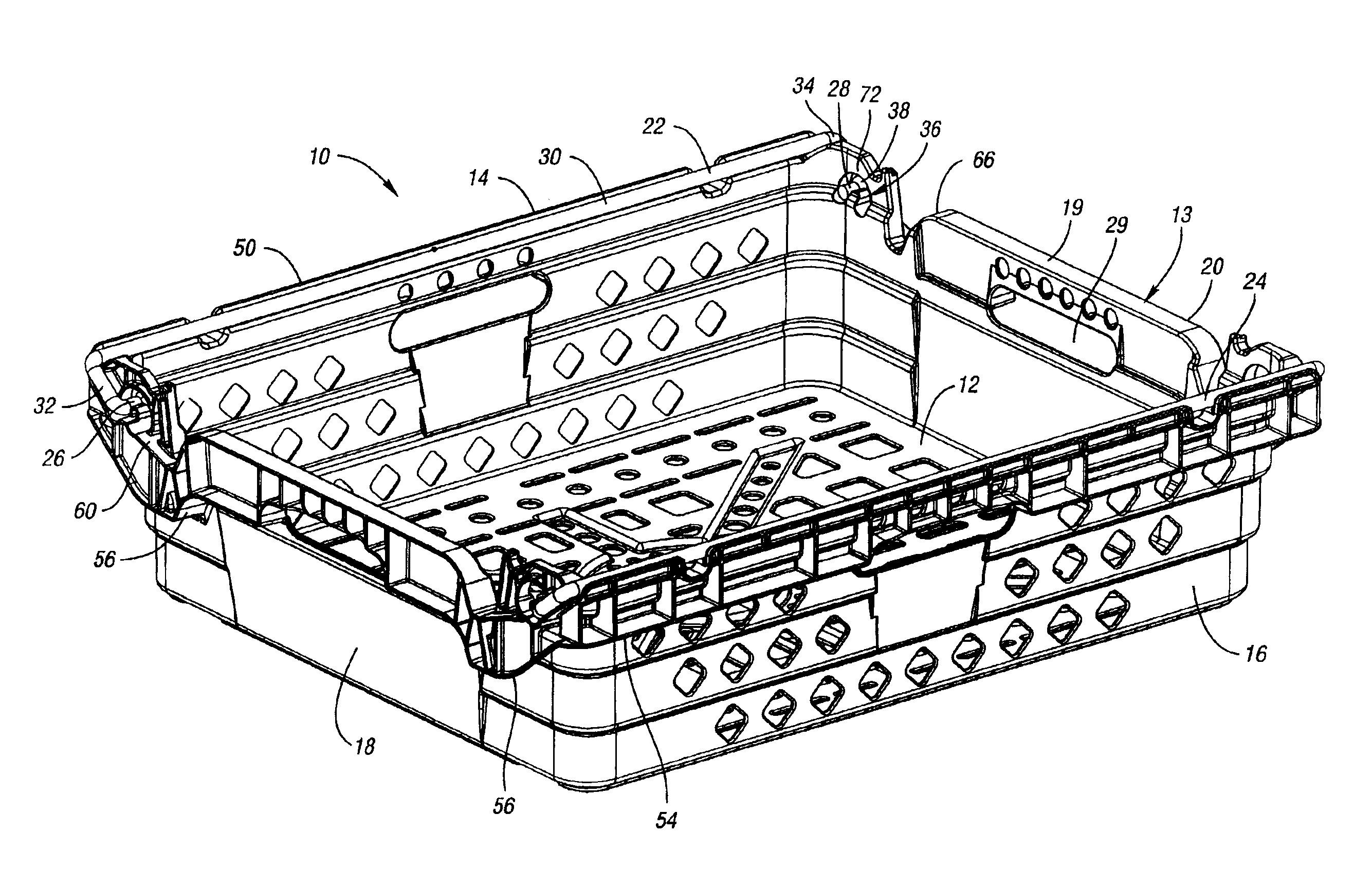
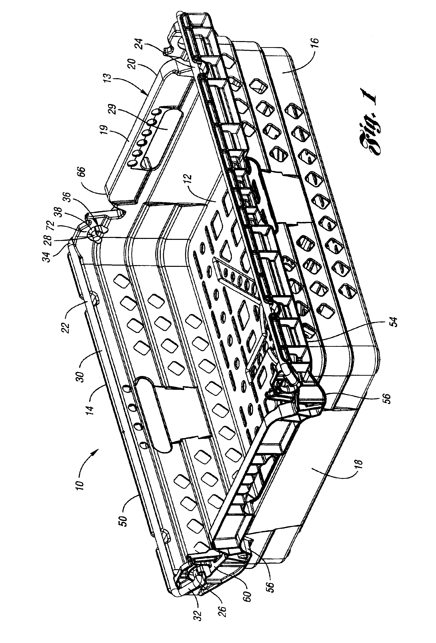
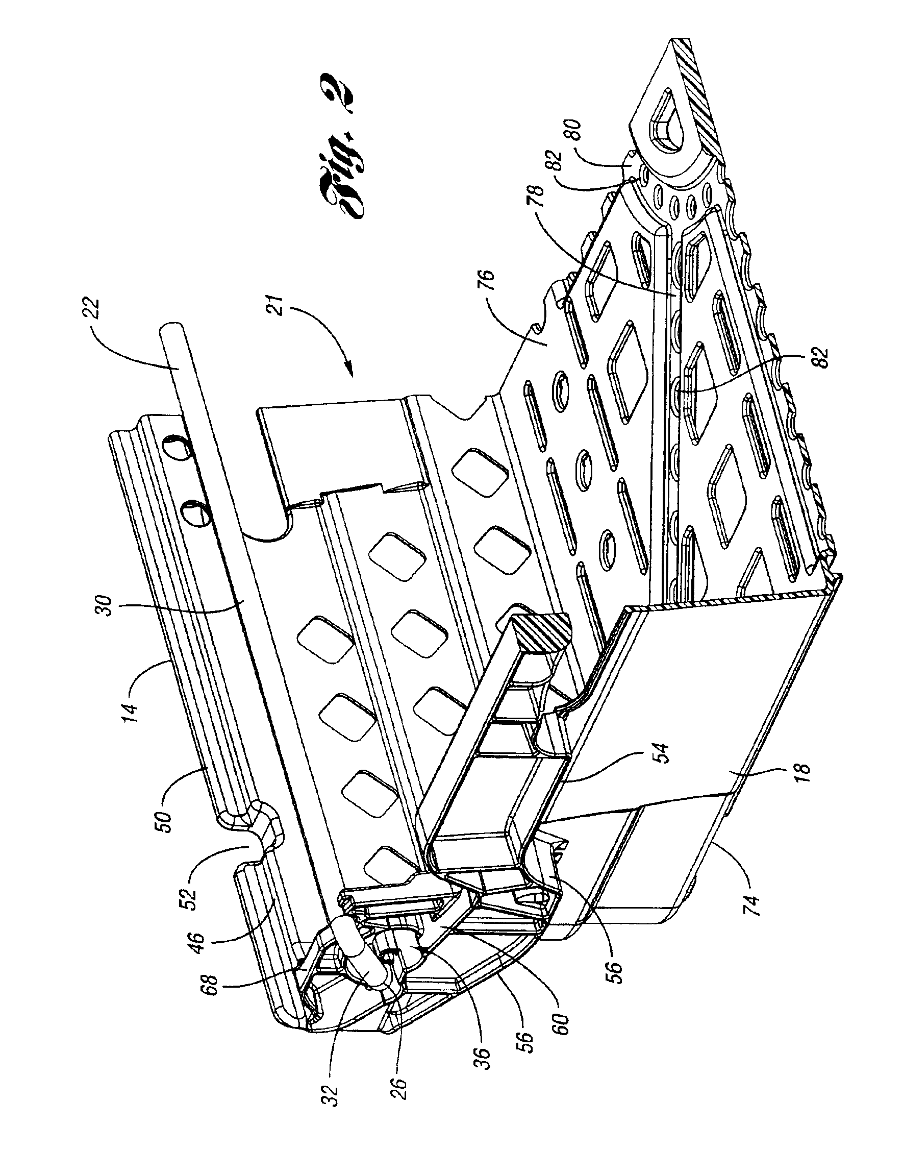
[0033]A container 10 according to the present invention is illustrated in FIGS. 1-11. Container 10 is preferably portable and includes a floor member 12 and an upstanding wall structure 13 extending upwardly from floor member 12. Upstanding wall structure 13 includes a first pair of upstanding opposed side walls 14, 16 and a second pair of upstanding opposed side walls 18,20 (also referred to as end walls.) Floor member 12 and walls 14-20 are integrally molded to form a unitary construction having a compartment area 21 within which goods are stored and transported. Container 10 preferably is formed from injection molded thermoplastic such as polyethylene. Container 10 also includes a pair of opposed support members 22,24 (also known in the art as bail arms or bail members), each of which is selectively moveable and pivotable among a plurality of positions, with at least three such positions illustrated herein.

[0034]For ease of discussion, reference will be made to bail arm 22, it b...


PUM


Abstract

A storage container has a floor and two pairs of opposed walls extending upwardly from the floor. Included is a bail member having bail ends mountable to one of the pairs of walls, and movable among nest and stack positions. Also included are mounting portions on one of the pairs of walls for receiving the bail ends. Mounting portions include an opening defining a plurality of pivot axes about which the bail member pivots, each axis oriented at substantially similar heights above the floor. When bail ends are positioned at one pivot axis, bail member is movable between the nested and a first stack positions. When bail ends are positioned at an other pivot axis, bail member is oriented in the second stack position. To move the bail member between first and second pivot axes, the bail member is raised upwardly within the opening and moved around an interference portion.

Description

BACKGROUND OF THE INVENTION[0001]1. Field of the Invention[0002]This invention relates to storage containers which are portable, and which are capable of stacking and nesting with similar containers.[0003]2. Background Art[0004]Portable storage containers which both stack and nest with similar containers are commonly used in industry for transporting and storing goods. Nesting is typically achieved when an empty container receives a like container therein such that there is some overlap between the walls and the containers. On the other hand, the stacking feature is typically used when an occupied container has a like container supported thereon, such that there is relatively little or no overlap between the walls of the containers, and the goods contained in the lower container are preferably not contacted or damaged by the upper container. Many containers use members known bail arms to achieve the stacking feature. Bail arms may typically be positioned out of the way for purposes ...

Claims


Application Information

Patent Timeline
Patent Type & Authority Patents(United States)
IPC IPC(8): B65D21/06
CPCB65D21/062
Inventor AIKEN, CYNTHIA R.APPS, WILLIAM P.
Owner REHRIG PACIFIC CO INC
Why Eureka
Try Eureka