Snowboard binding

a technology for snowboards and straps, applied in the field of snowboard bindings, can solve the problems of cumbersome inability to accurately perform, and difficulty in achieving, and achieve the effect of improving the snowboard binding, simple and accurate adjustment of effective length of instep straps

Inactive Publication Date: 2005-09-06
NIDECKER
View PDF17 Cites 109 Cited by
  • Summary
  • Abstract
  • Description
  • Claims
  • Application Information

AI Technical Summary

Benefits of technology

[0006]An object of this invention is to improve the snowboard binding described above such

Problems solved by technology

The adjustment of the position and thus, the effective length of the instep strap is cumbersome in practice, and either cannot be performed accurately enough or requires several adjustment steps.
On the other hand, many snowboarders like to loosen the binding, i.

Method used


Image

  • Snowboard binding
  • Snowboard binding
  • Snowboard binding

Examples


Embodiment Construction

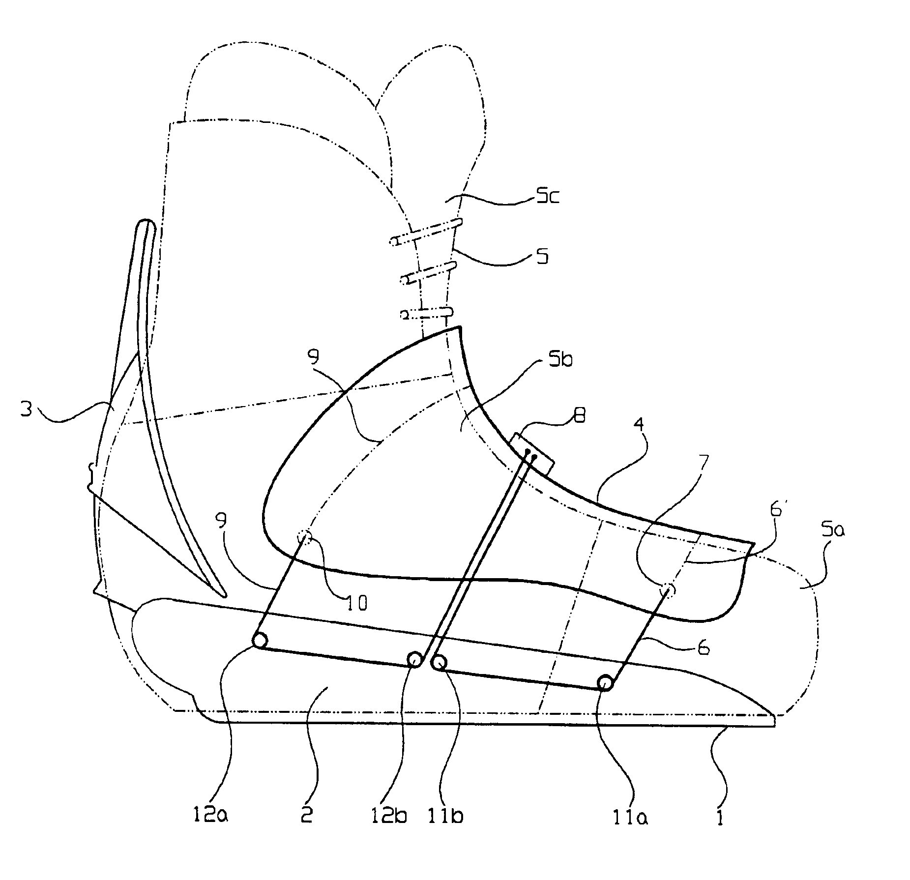
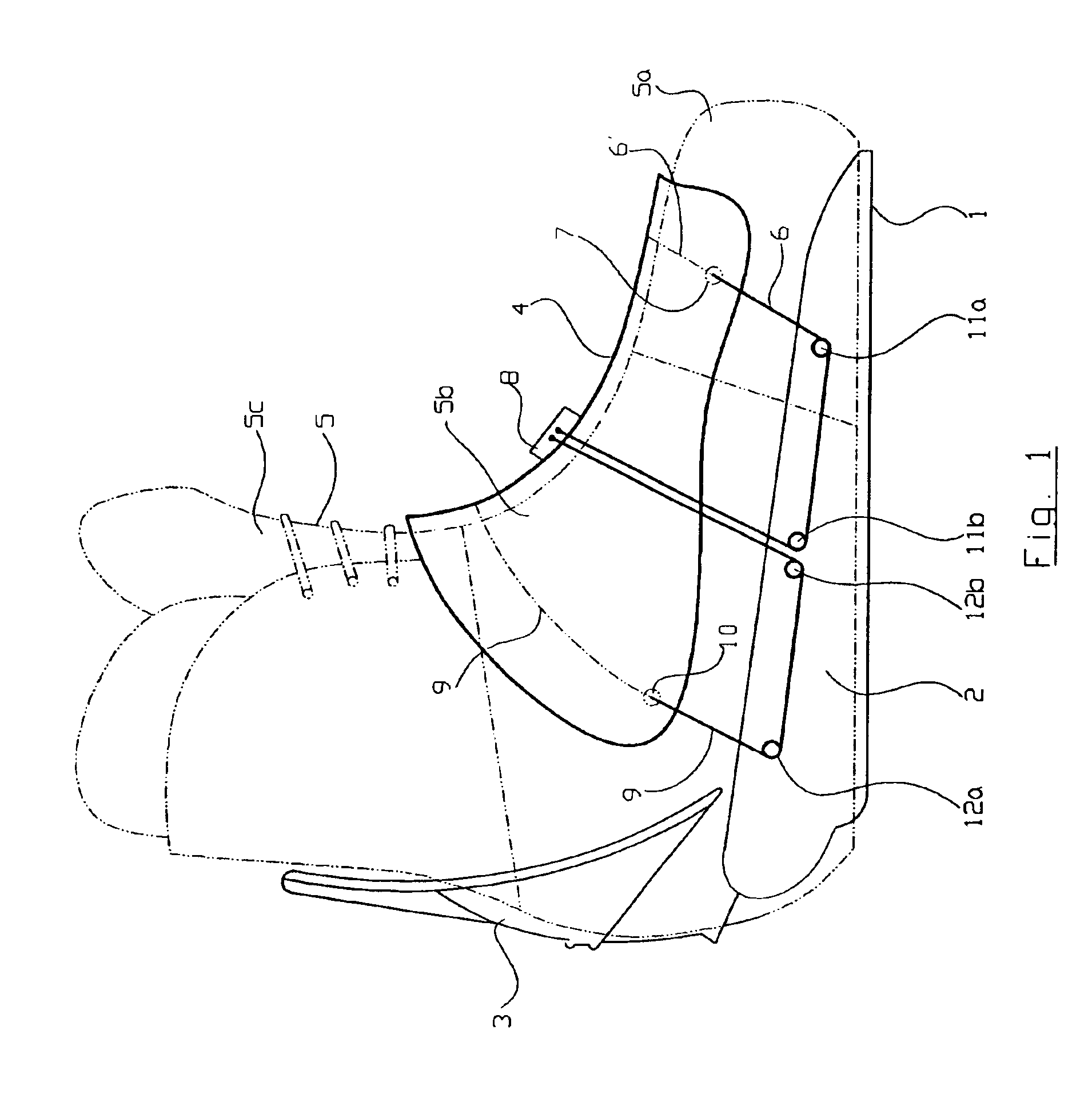
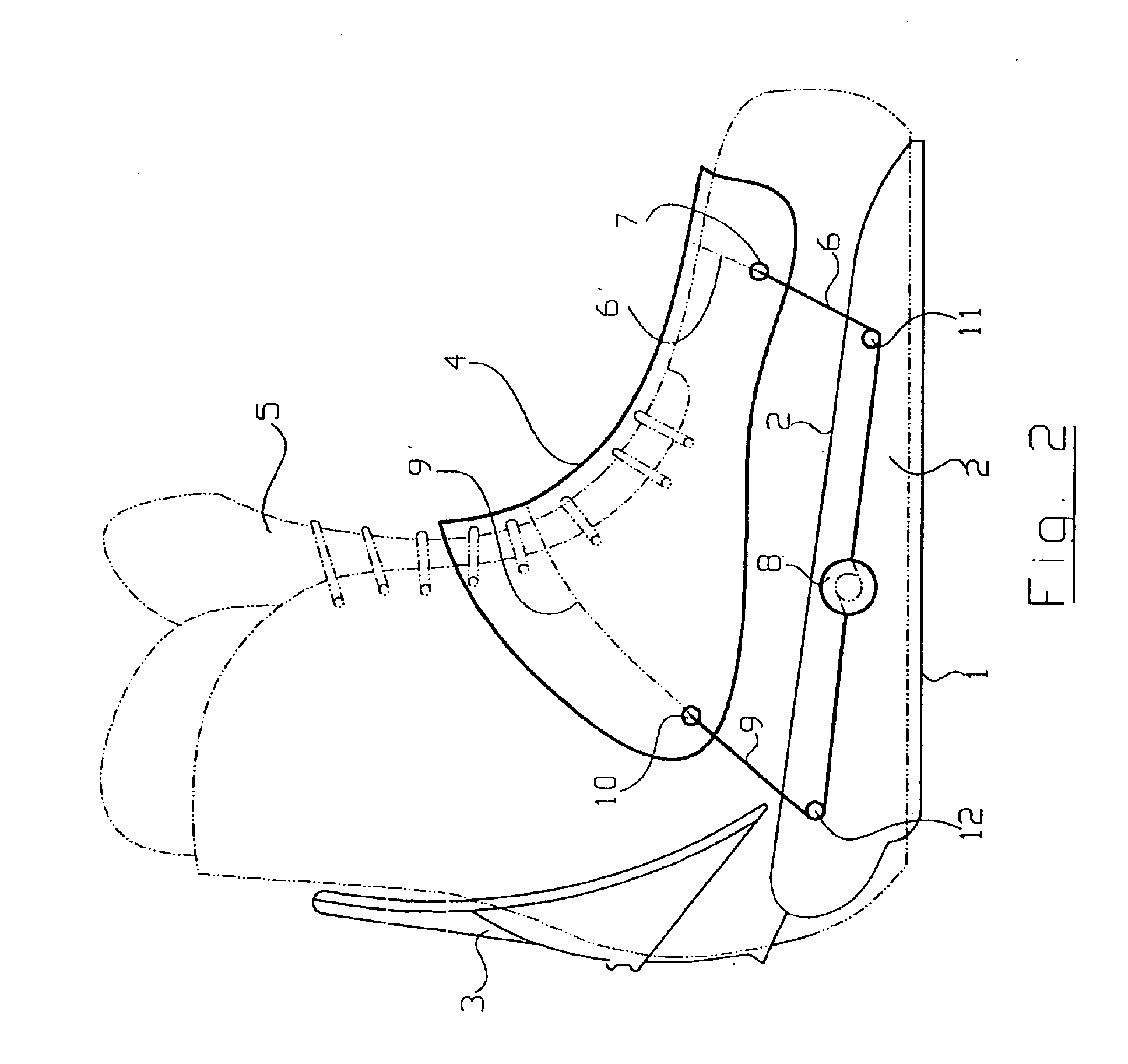
[0018]At first, reference will be made to FIG. 1. A snowboard binding has a support structure with a base plate 1, which is attached in a known way to the surface of a snowboard (not shown). This is typically done with screws. Side plates 2, which extend perpendicularly from the base plate 1 and are attached to the actual base plate 1 on both sides of a boot 5, are integral components of the support structure. The side plates 2 have several functions, among other things, lateral guidance of the boot, pivotally holding a heel part 3, and holding a single instep strap 4 that extends from a front toe region 5a of the boot 5 to an instep region 5b and partially crosses over into an upper shoe region 5c. Although not only the instep but also the toe region and possibly also an upper shoe part are covered, here it is called an instep strap. This instep strap 4 is attached to at least one side plate 2 by tension cables 6 and 9. While numerous embodiments are possible four are described in ...


PUM


Abstract

A snowboard binding has a support structure with a base plate and side plates that project from the base plate. Tension cables, which hold a single instep element, are attached to the side plates. The instep element extends from a toe region of the boot up to at least its instep region. A single tensioning device for the tension cables is independent of a pivoting position of a heel element.

Description

BACKGROUND OF THE INVENTION[0001]This invention relates generally to a snowboard binding.[0002]Known snowboard bindings, such as the one described in WO 00 / 76602 A2, have a base plate screwed onto the surface of a snowboard and two side plates extending upwards from the base plate. Two straps are attached to the side plates. One strap crosses over an instep of a boot and the other crosses over a toe area, the portion of the boot that can be inserted into the binding. In this disclosure, both straps are connected to the two side plates by tension cables and can be tensioned by means of a tensioning element, which winds the tension cables onto winding spindles. This allows the effective length of the straps crossing the boot to be adjusted. The tension cables are guided over the straps twice by forming two-sided loops and the tensioning element is attached to each strap.[0003]In DE 91 13 766 U1 and U.S. Pat. No. 5,727,797, the straps are connected to the side plates by a ratchet mecha...

Claims


Application Information

Patent Timeline
IPC IPC(8): A63C9/00A63C5/00A63C10/04A63C10/06A63C10/24
CPCA63C10/04A63C10/06A63C10/24
Inventor ELKINGTON, MARK
Owner NIDECKER
Why Eureka
Try Eureka