Growth factor releasing biofunctional dental implant

a biofunctional, growth factor-releasing technology, applied in dental implants, dental surgery, medical science, etc., can solve the problems of crown breakage, screw loosening and screw breakage, and conventional implants are often too rigid to function like natural teeth

Inactive Publication Date: 2005-09-06
SAPIAN SCHUBERT L
View PDF13 Cites 74 Cited by
  • Summary
  • Abstract
  • Description
  • Claims
  • Application Information

AI Technical Summary

Problems solved by technology

However, conventional implants are often too rigid to function like natural teeth.
Problems such as crown breakage, screw loosening and screw breakage are inherent problems with a rigid crown implant.
Failure is also known to occur when an implant is used in a bridge abutment with a natural tooth or when improper occlusion is created by the implant crown.
More particularly, screws associated with conventional crowns sometimes break because of over tightening and due to tension and lateral stress to which the crown is subjected during use.
As dental professionals will understand, it is difficult and time consuming to retrieve and / or repair such broken screws.
Once the root portion of the implant is installed, it may take several months to achieve suitable bone integration of the root portion with the surrounding bone structure thereby resulting in increased loading time before the crown can be reliably anchored.
What is still more, many crowns are not adapted to move under loading conditions and, consequently, they cannot easily absorb and distribute shock and other physical forces that are generated during chewing.
Such crowns may be susceptible to damage or reduced life and may be unable to provide the function of a natural tooth and the quality of mastication associated therewith.

Method used


Image

  • Growth factor releasing biofunctional dental implant
  • Growth factor releasing biofunctional dental implant
  • Growth factor releasing biofunctional dental implant

Examples


first embodiment

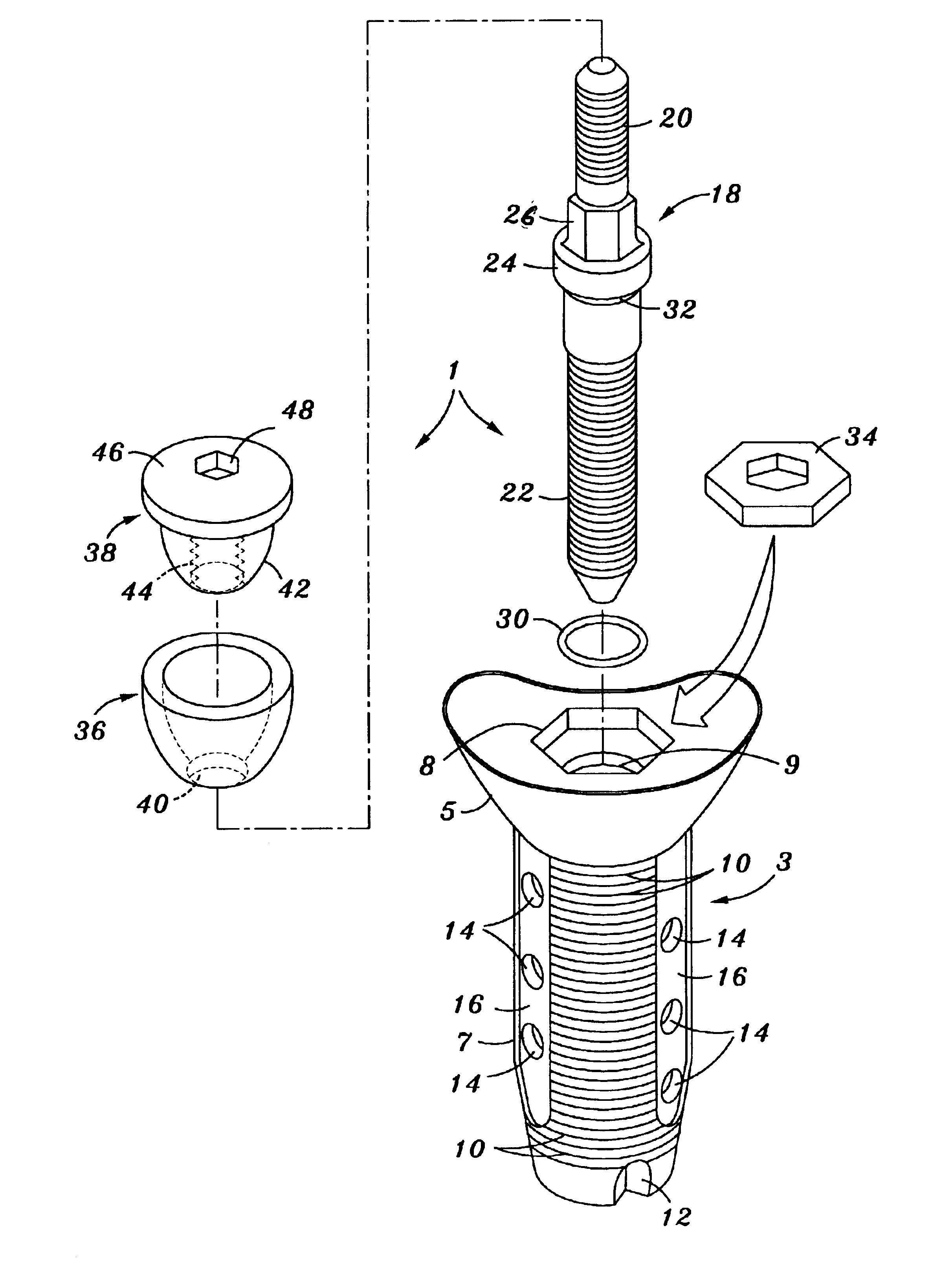
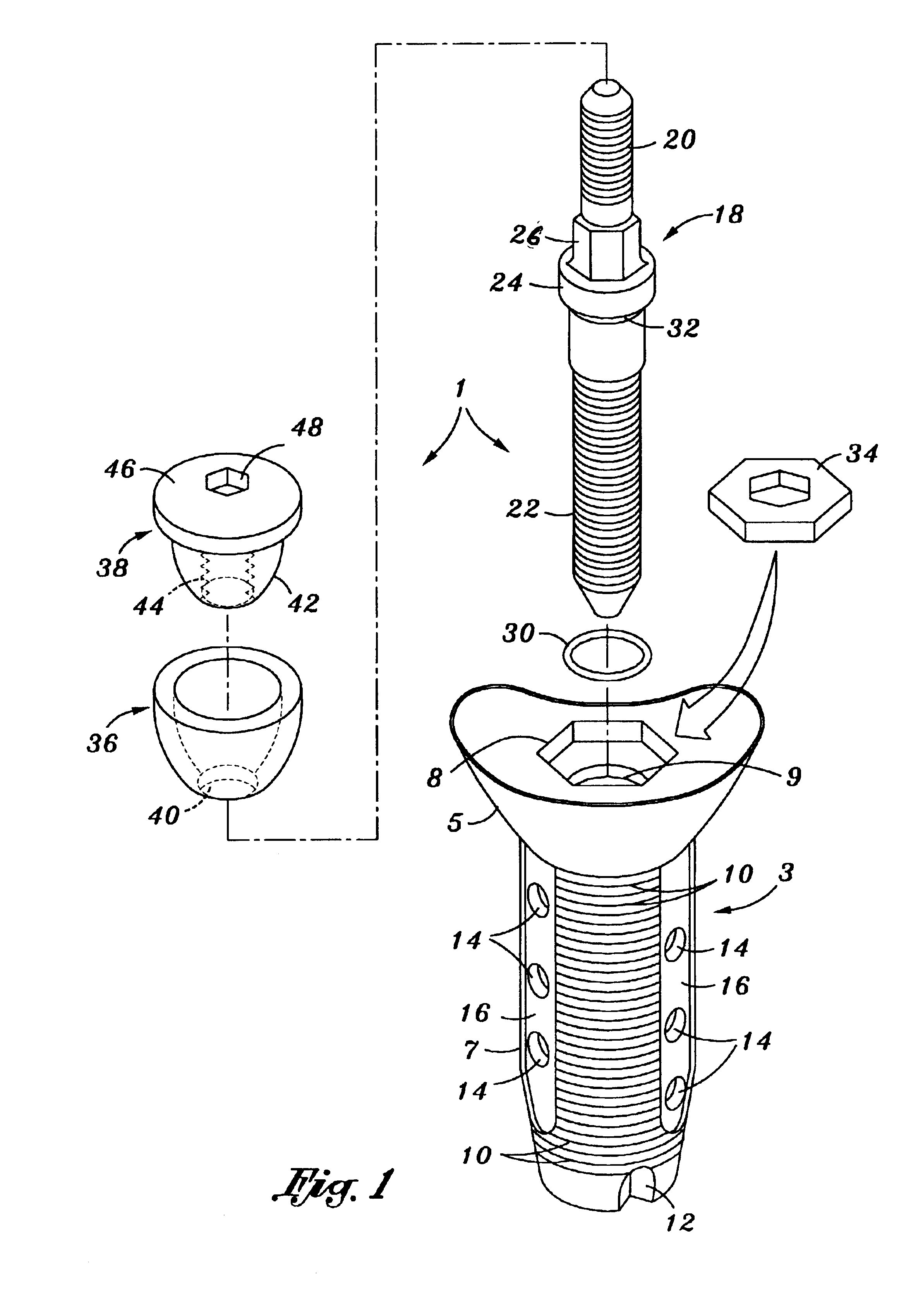
[0019]Referring to FIG. 1 of the drawings, there is shown an exploded view of an implant bone locking mechanism 1 which forms this invention. The implant bone locking mechanism 1 includes a root portion 3 that is preferably manufactured from a biocompatible metallic (e.g. titanium or titanium alloy) or ceramic material that is adapted to be implanted in a socket formed in the bone structure of a dental patient in a manner that will be described in greater detail when referring to FIG. 2. The root portion 3 includes a relatively wide, outwardly flared implant cradle 5 and a relatively narrow, generally cylindrical implant casing 7 which depends downwardly therefrom. As is best shown in FIG. 2, the implant casing 7 of root portion 3 is implanted (by means of a suitable tool 60) within an implant socket that is made in the patient's bone structure so that the implant cradle 5 can support a crown portion (designated 50 in FIG. 5) above the gum line.

[0020]As shown in FIG. 1, the outwardl...

second embodiment

[0036]An exploded view of an implant bone locking mechanism 100 which forms this invention is now disclosed while referring initially to FIG. 6 of the drawings. Like the locking mechanism 1 of FIGS. 1-5, the implant bone locking mechanism 100 of FIG. 6 includes a metallic (e.g. titanium or titanium alloy) or ceramic root portion 103 that is adapted to be implanted in a socket formed in the bone structure of a dental patient. The root portion 103 includes a relatively wide, outwardly flared implant cradle 105 and a relatively narrow, generally tubular and slightly tapered implant casing 107 depending downwardly therefrom. With the root portion 103 positioned within the implant socket, the implant cradle 105 will be supported above the patient's gum line to receive a crown portion (designated 170 in FIG. 8).

[0037]The top of implant cradle 5 may be covered with a low friction (e.g. Teflon) coating to minimize friction at the interface of the crown portion 170 with the implant cradle. W...


PUM


Abstract

A biofunctional dental implant system for affixing a crown to an implant socket that is made in the bone structure within the mouth of a dental patient. A root portion is initially anchored within the implant socket made in the patient's bone structure. According to a first embodiment of this invention, the crown is secured to the root portion by a flexible abutment post. According to a second embodiment, the crown is secured to the root portion by a hollow abutment tube. The dental implant system of this invention is capable of increasing bone/implant stabilization and providing a supply path through which to evenly distribute human growth factor to the bone structure surrounding the root portion. The system also enables the crown to have a selectively controllable mobility relative to the root portion that is anchored within the implant socket so as to advantageously function like a natural tooth.

Description

BACKGROUND OF THE INVENTION[0001]1. Field of the Invention[0002]This invention relates to a biofunctional dental implant including a dental crown and an implant bone locking mechanism by which to anchor the crown within an installation socket that is made in the patient's bone structure to facilitate a reliable bone implant, increase bone / implant stabilization and provide a supply path through which human growth factor can be evenly distributed to the bone structure surrounding the locking mechanism. The crown and the implant bone locking mechanism are coupled to one another to permit the crown to have mobility relative to the locking mechanism and thereby function like a natural tooth.[0003]2. Background Art[0004]Natural teeth in the human mouth are supported in bone by periodontal fibers that function as shock absorbers when a compressive force is applied, such as during chewing. Through disease, accidental injury, anatomical abnormalities, age, and the like, a natural tooth may b...

Claims


Application Information

Patent Timeline
Patent Type & Authority Patents(United States)
IPC IPC(8): A61C8/00
CPCA61C8/005A61C8/0065A61C8/0077A61C8/0086A61C8/0006A61C8/0009A61C8/0054A61C8/0057A61C8/0059A61C8/006A61C8/0069A61C8/0033
Inventor SAPIAN, SCHUBERT L.
Owner SAPIAN SCHUBERT L
Why Eureka
Try Eureka