
Filter device for filtering fluids

Active Publication Date: 2005-09-06
NORDSON CORP
View PDF6 Cites 0 Cited by
  • Summary
  • Abstract
  • Description
  • Claims
  • Application Information

AI Technical Summary

Benefits of technology

[0006]The present invention provides a device for attaching a filter element to a filter housing using a bayonet-type configuration. The manner of attachment according to the present invention achieves secure, positive-lock attachment of the filter element to the filter housing. The attachment may be releasable in a short amount of time by a simple motion, such as a small rotation. That reduces the time which is needed to release the filter element from the filter housing or to remove it therefrom. The filter device according to the present invention, when used in conjunction with a device which further processes the fluid being filtered, permits a short down time of the device when filter replacement or filter removal is necessary.
[0007]According to one aspect of the invention, the attaching device is movable between a closed position, in which the filter element is attached in a cavity of the filter housing and this cavity is sealed off from the surroundings, and an open position, in which the filter element may be removed from the filter housing. The cavity is connected with at least one fluid inlet and one fluid outlet. The filter element is positioned in the cavity in such a way that fluid which flows from the fluid inlet to the fluid outlet must pass through the filter element, and in so doing is filtered. The fluid to be filtered is normally under elevated pressure compared to the ambient pressure, but could also be at a lower pressure than the ambient pressure. In order to prevent fluid from escaping from the cavity into the surroundings, or environmental media, such as air, from entering the cavity from the surroundings, it is therefore necessary to seal the cavity off from the surroundings.
[0008]Advantageously, the attaching device may also be moved to a relief position located between the open and closed positions. In this relief position, the filter element is attached to the filter housing and the cavity is not sealed off from the surroundings. This embodiment is especially advantageous in order ensure safe removal of the filter element from the cavity. Since the fluid in the cavity is normally at a different pressure than the environment surrounding the filter device, as stated earlier, the resulting pressure difference may make removal of the filter element from the cavity more difficult and / or may lead to a risk of injury to the operating personnel of the filter device when performing the removal. It is conceivable, for example, that when the attaching device is moved from the closed to the open position, an overpressure in the cavity may cause parts of the attaching device to separate from the attaching device at high speed and injure the operator. It is also conceivable that the fluid which is under pressure may escape from the cavity at the moment the cavity is opened. Since health-endangering fluids or fluids at high temperature may be involved, uncontrolled escape of the fluid under high pressure is undesirable. It is also conceivable that the removal of the filter element or parts of the attaching device may be made more difficult by underpressure in the cavity. The relief position provided by the present invention makes it possible to reduce the pressure difference between the cavity and the surroundings in a controlled manner, without the filter element becoming detached from the housing prematurely.

Problems solved by technology

Since the fluid in the cavity is normally at a different pressure than the environment surrounding the filter device, as stated earlier, the resulting pressure difference may make removal of the filter element from the cavity more difficult and / or may lead to a risk of injury to the operating personnel of the filter device when performing the removal.
It is conceivable, for example, that when the attaching device is moved from the closed to the open position, an overpressure in the cavity may cause parts of the attaching device to separate from the attaching device at high speed and injure the operator.
Since health-endangering fluids or fluids at high temperature may be involved, uncontrolled escape of the fluid under high pressure is undesirable.
It is also conceivable that the removal of the filter element or parts of the attaching device may be made more difficult by underpressure in the cavity.

Method used


Image

  • Filter device for filtering fluids
  • Filter device for filtering fluids
  • Filter device for filtering fluids

Examples


Embodiment Construction

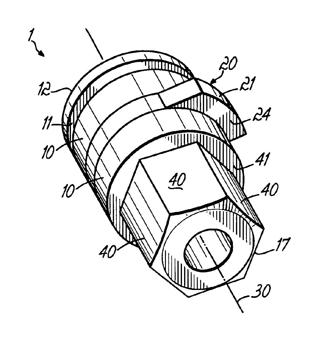
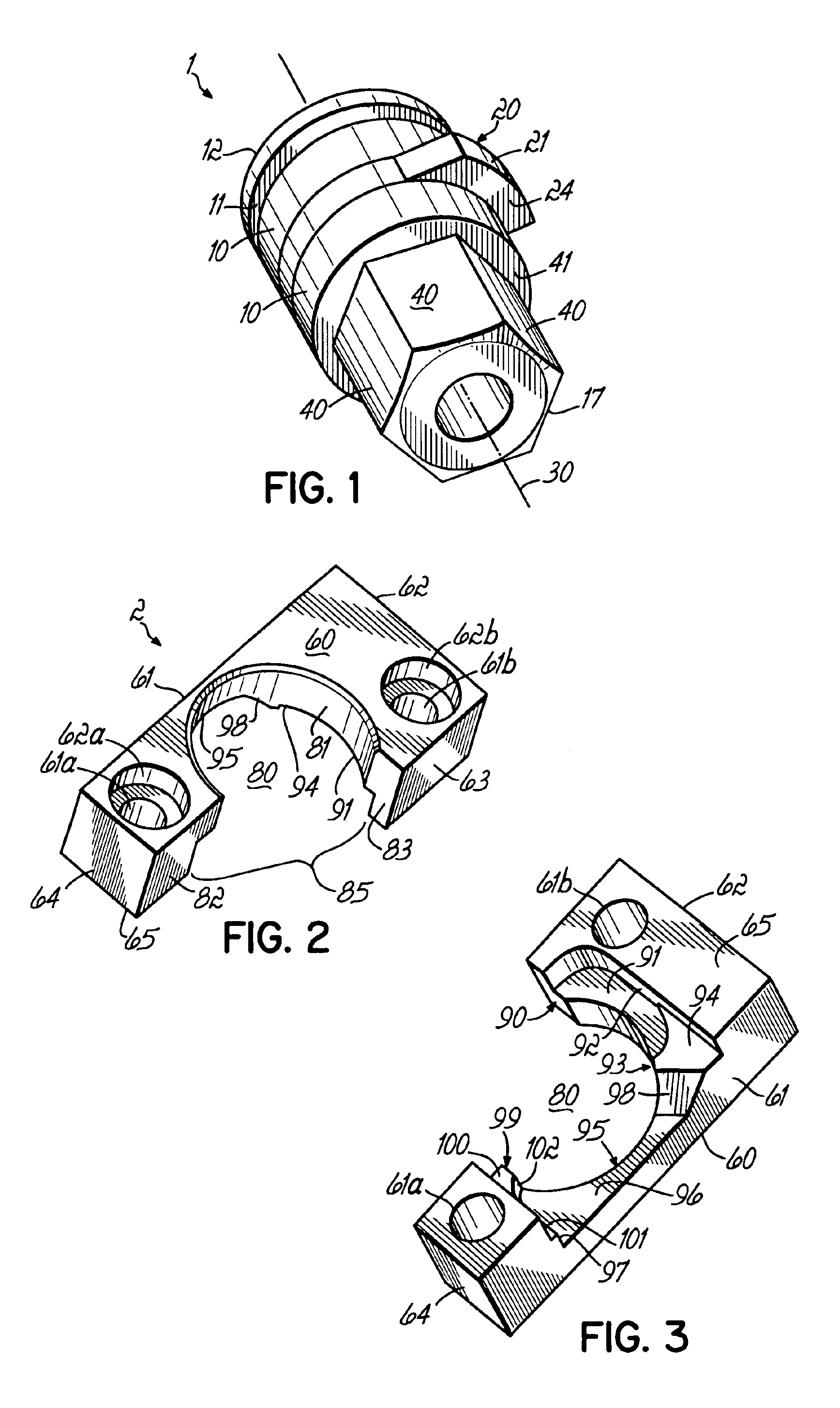
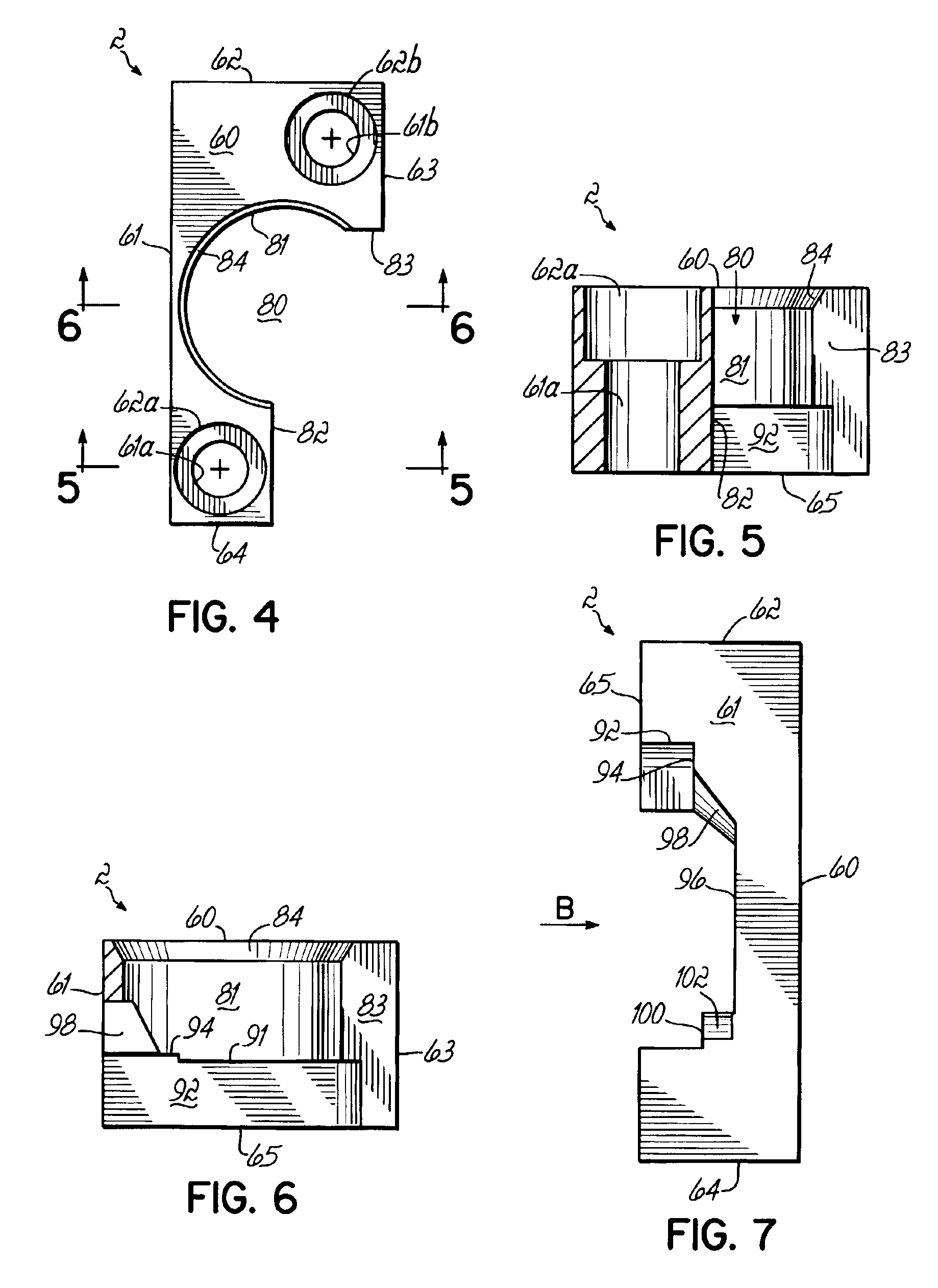
[0044]Referring to FIG. 1, a first attaching element 1 of an exemplary attaching device of the filter device according to the present invention has a cylindrical surface 10, on which an elevation 20 is formed. Cylindrical surface 10 is arranged in rotational symmetry around an axis 30. Elevation 20 extends in a radial direction from axis 30. In addition, there are hexagonal surfaces 40 formed around rotational axis 30 of the first attaching element 1, to facilitate engagement of first attaching element 1 with a tool, for example, to permit applying a torque to the first attaching element 1.

[0045]Referring to FIGS. 2-9, a second attaching element of the attaching device of the filter device according to the present invention, constructed as a cover plate 2, has an outer surface 60 to which there two boreholes 61a, 61b in perpendicular orientation. Boreholes 61a, 61b have cylindrical counter-bores 62a, 62b, so that conventional commercial socket-head cap screws may be inserted through...


PUM

PropertyMeasurementUnit
Angleaaaaaaaaaa
Shapeaaaaaaaaaa

Abstract

A filtering device for filtering fluids includes a filter housing, a filter element and an attaching device for attaching the filter element to the housing. The filter element is attachable to the filter housing using a bayonet lock.

Description

FIELD OF INVENTION[0001]The present invention relates to a filter device for filtering fluids, comprising a filter housing, a filter element and an attaching device for attaching the filter element to the housing. The present invention also relates to an application device having such a filter device.BACKGROUND[0002]Filter devices of the named type are known and are used in a large number of technical applications, especially in order to filter particles above a certain size out of a stream of liquid or gas. Filter devices of this sort are normally constructed in such a way that a filter element is removably attached to a housing using an attaching device. It is thus possible to release the filter element from the housing and remove it therefrom, in order to check it, clean it, replace it or the like.[0003]In many applications, such removal of the filter element must be performed at short time intervals.[0004]In the related art, attaching devices are known which provide such attachm...

Claims


Application Information

Patent Timeline
IPC IPC(8): B01D46/42B01D46/00B01D46/24B01D29/11
CPCB01D46/008B01D46/24B01D2265/022B01D2271/027B01D46/88
Inventor SEEDORF, HANS-JOACHIM
Owner NORDSON CORP
Learn More