
Cathode ray tube

a cathode ray tube and cathode ray tube technology, applied in cathode ray tubes/electron beam tubes, electric discharge tubes, electrical equipment, etc., can solve the problems of reducing the outer diameter of the funnel yoke installation part, consuming power is critical, electron beams cannot reach the fluorescent screen, etc., to achieve the effect of strengthening the close contact, reducing the productivity of the funnel, and weakening the deflection sensitivity

Inactive Publication Date: 2005-09-06
MERIDIAN SOLAR & DISPLAY
View PDF5 Cites 2 Cited by
  • Summary
  • Abstract
  • Description
  • Claims
  • Application Information

AI Technical Summary

Benefits of technology

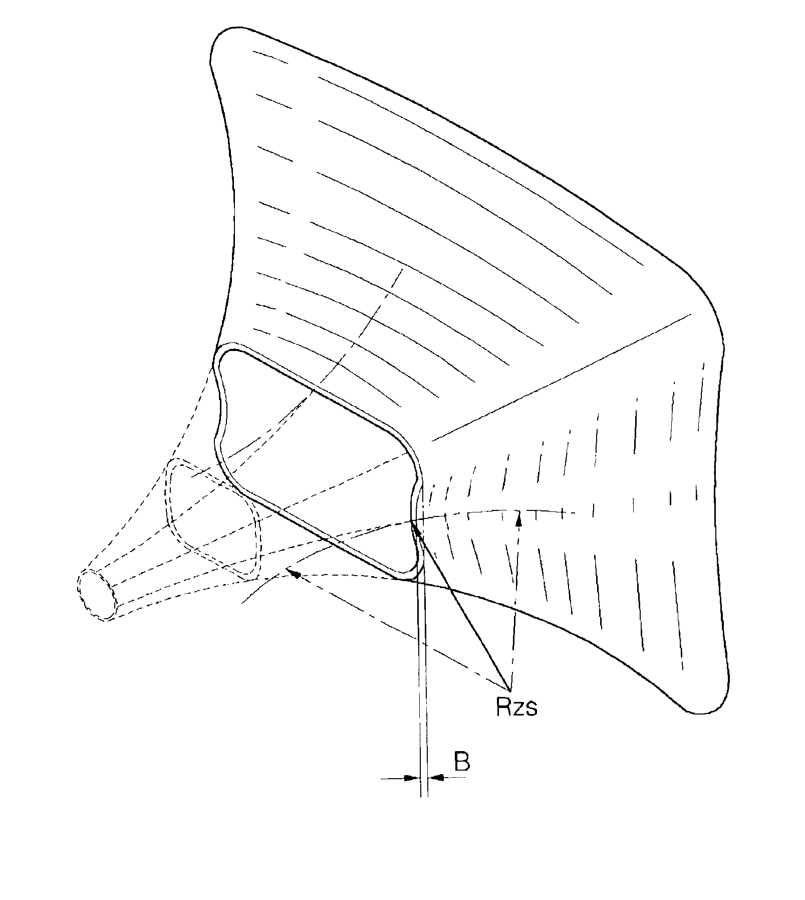
[0035]An object of the present invention is to enhance the close contactness between the funnel and the deflection yoke without decreasing the productivity of the funnel, weakening the deflection sensitivity and increasing the power consumption so that although the deflection yoke is moved toward the neck of the funnel, the electron beams do not strike the yoke installation part to enhance the BSN neck shadow margin and the deflection efficiency.

Problems solved by technology

For such a color cathode ray tube, consuming power is critical problem.
Accordingly, the conventional cathode ray tube is limited to reduce the outer diameter of the funnel yoke installation part.
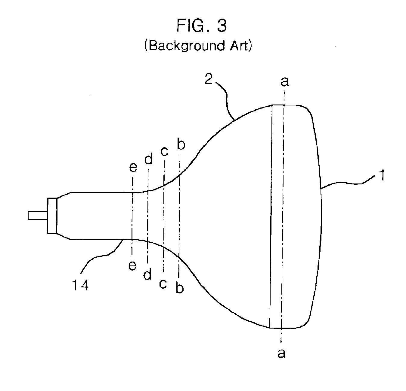
However, since the deflection sensitivity is improved and the movement of the electron beam gets very sensitive to the deflection yoke control, it causes a beam strike neck (BSN) phenomenon in which electron beam collides an inner wall of the yoke installation part 14 of the funnel so that the electron beam cannot reach a fluorescent screen.
However, these methods causes the side effect to deteriorate the deflection sensitivity of the deflection yoke and cause the deflection yoke to require more consuming power.
However, it lowers the productivity of the funnel to make the funnel thin, which is formed to have the minimal thickness.
However, it has no effect to gain the BSN neck shadow margin.

Method used


Image

  • Cathode ray tube
  • Cathode ray tube
  • Cathode ray tube

Examples


Embodiment Construction

[0055]Reference will now be made in detail to the preferred embodiments of the present invention, examples of which are illustrated in the accompanying drawings. Wherever possible, the same reference numbers will be used throughout the drawings to refer to the same or like parts.

[0056]Table 1 illustrates the thickness of the yoke installation part of a general funnel for cathode ray tube.

[0057]

TABLE 1Thickness ofThickness ofThickness oflonger sideshorter sidediagonal sideLocation (mm)(mm)(mm)(mm)+354.554.653.23+304.033.932.91+253.753.752.63+203.583.602.49+153.483.532.38+103.353.432.35+5 3.253.302.36Reference line3.053.102.36(RL)−5 2.852.852.30−102.682.632.35−152.602.632.45−202.582.632.59−252.552.732.78−302.782.782.81

[0058]As shown in table 1, the thickness of the funnel in the direction (+) to the funnel is different from the thickness of the funnel in the direction (−) to a neck. Especially, the diagonal side is formed thinner than any other sides and the shorter side is formed thi...


PUM


Abstract

The present invention relates to a cathode ray tube, and more particularly, to a funnel for CRT to increase the BSN neck shadow margin by changing the shape of the yoke portion.

Description

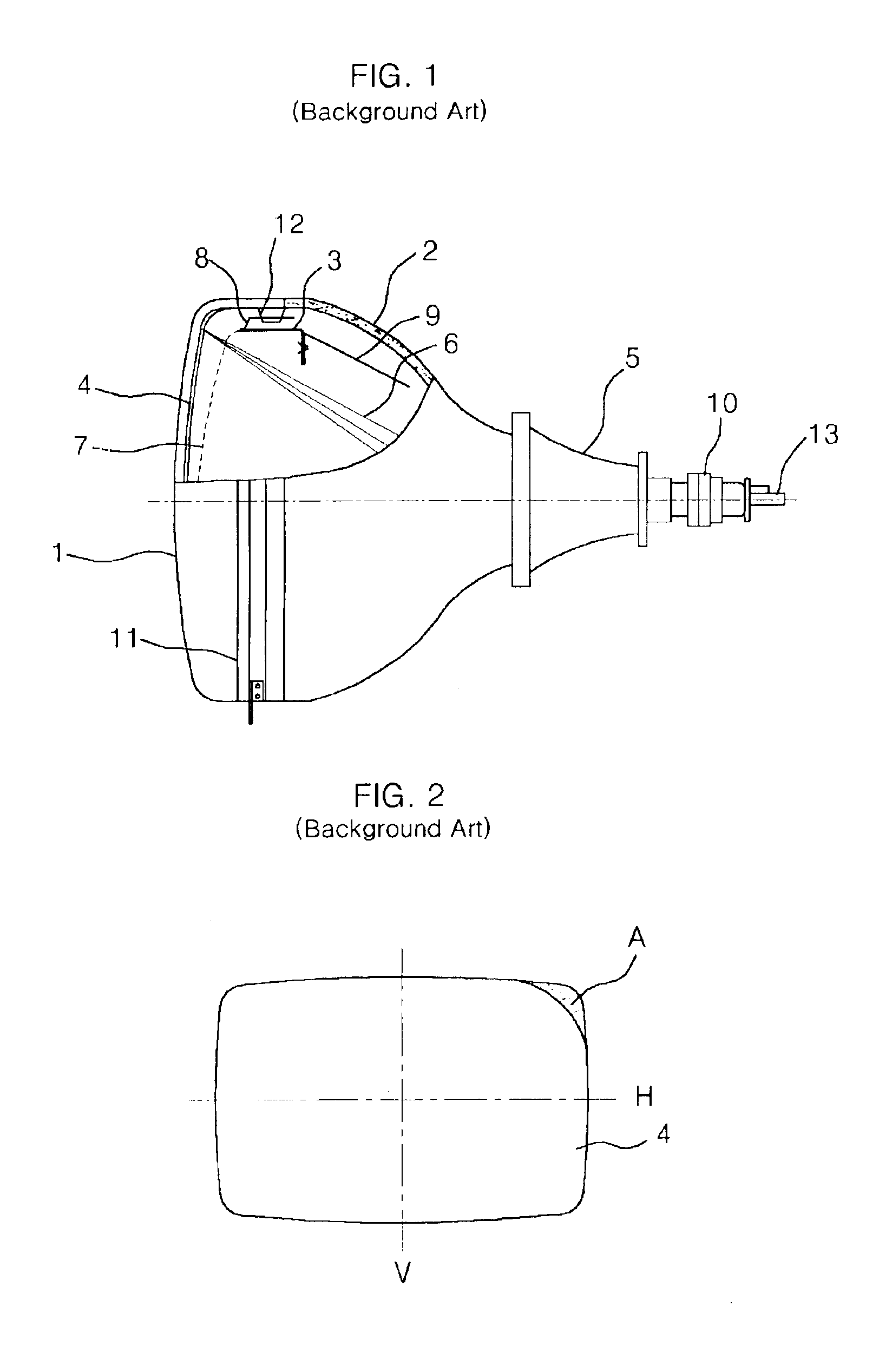
BACKGROUND OF THE INVENTION[0001]1. Field of the Invention[0002]The present invention relates to a cathode ray tube (CRT), and more particularly, to a funnel for a CRT to increase the BSN neck shadow margin by changing the shape of a yoke portion.[0003]2. Description of the Related Art[0004]FIG. 1 illustrates the configuration of a flat color cathode ray tube according to the related art.[0005]Referring to FIG. 1, the flat color cathode ray tube is a kind of vacuum tube that includes a panel 1 which is a front glass and a funnel 2 which is a rear glass sealingly coupled with the panel 1 so that the flat color cathode ray tube is vacuum inside.[0006]A fluorescent screen 4 is formed inside the panel 1. An electron gun 13 is installed at a neck portion of the funnel 2 opposed to the fluorescent screen 4.[0007]A shadow mask 7 is installed between the fluorescent screen 4 and the electron gun 13, spaced by a predetermined distance from the fluorescent screen 4 to select colors. The shado...

Claims


Application Information

Patent Timeline
Patent Type & Authority Patents(United States)
IPC IPC(8): H01J29/86H01J29/02
CPCH01J29/861H01J2229/8606H01J29/02
Inventor PARK, SANG YOON
Owner MERIDIAN SOLAR & DISPLAY
Learn More