Method for absolute calibration of an interferometer

an interferometer and absolute calibration technology, applied in the direction of optical radiation measurement, instruments, measurement devices, etc., can solve the problem of low number of absolute calibration methods of interferometers with spherical output waves

Inactive Publication Date: 2005-09-06
CARL ZEISS SMT GMBH
View PDF13 Cites 20 Cited by
  • Summary
  • Abstract
  • Description
  • Claims
  • Application Information

AI Technical Summary

Benefits of technology

[0007]It is the object of the present invention to create a novel absolute calibration method for interferometers with a spherical output wave, which can be used to measure at least as accurately as can be done with the aid of the previously known methods, a further possibility thereby being provided of assessing more effectively the accuracy of the absolute calibration.

Problems solved by technology

The main disadvantage of the known methods resides in the low number of absolute calibration methods for interferometers with a spherical output wave.

Method used


Image

  • Method for absolute calibration of an interferometer
  • Method for absolute calibration of an interferometer
  • Method for absolute calibration of an interferometer

Examples


Embodiment Construction

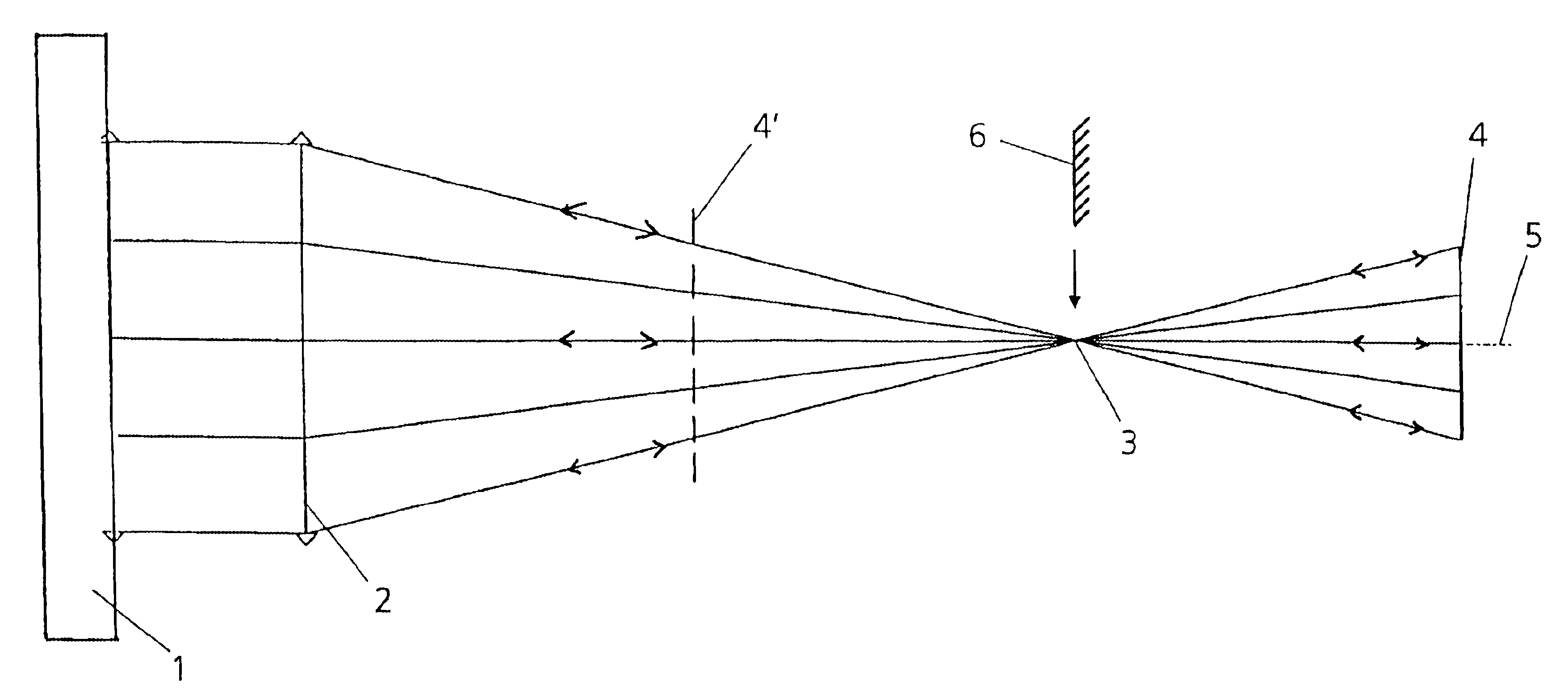
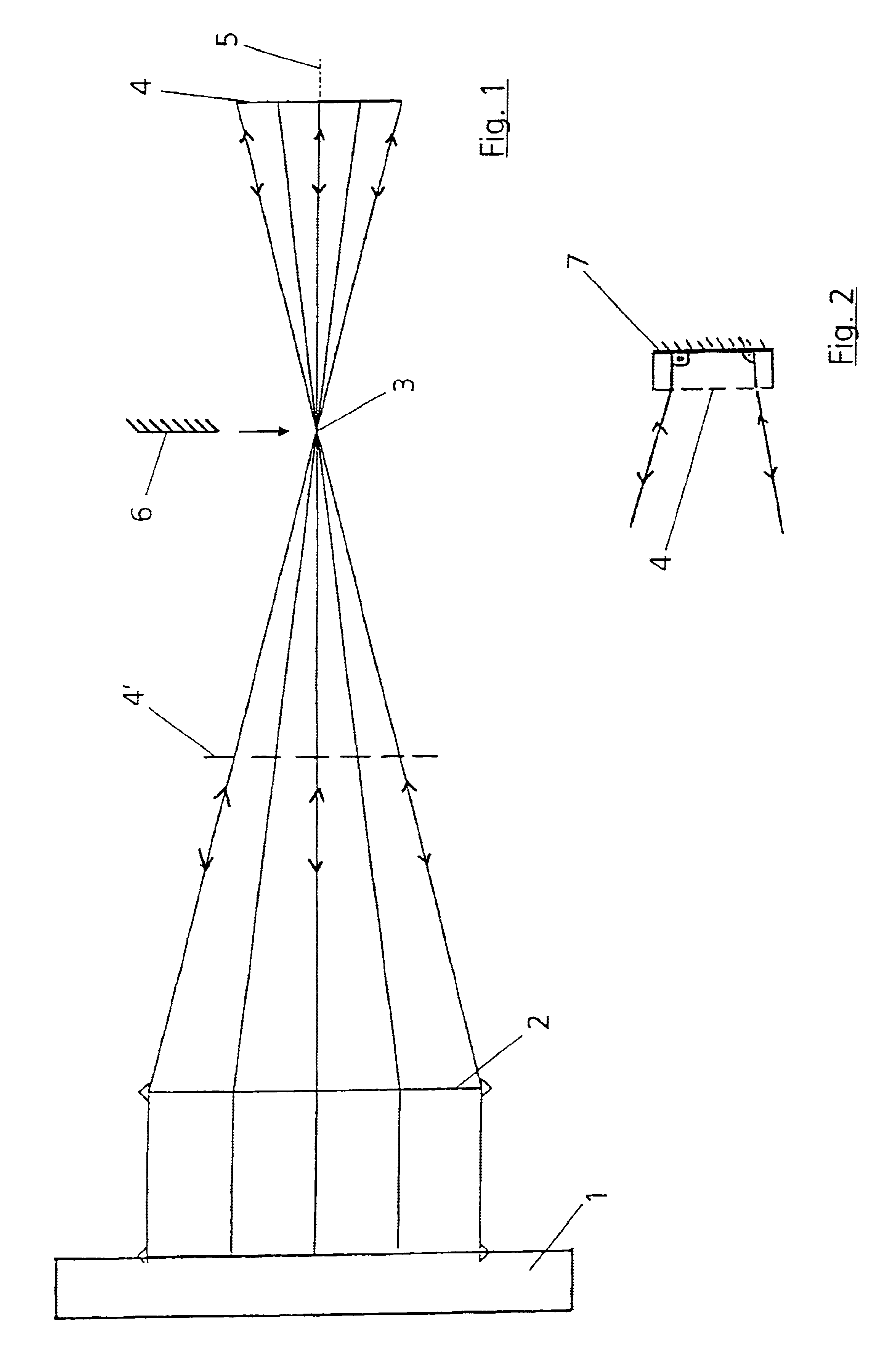
[0023]According to the exemplary embodiment in accordance with FIG. 1, five measurements are provided for absolute calibration of an interferometer 1 with a reference surface. For this purpose, a spherical output wave of the interferometer traverses a lens 2 downstream of which the wave converges. Arranged in the direction in which the beam runs downstream of a focus 3 after which the wave diverges again is a DOE 4 which serves as an optical element in reflection and retroflects the incoming spherical wave into itself. A first measurement is performed in this position. In a second measurement, the DOE 4 is rotated by 180° about the optical axis 5.

[0024]The DOE 4 is subsequently brought from the above-named extrafocal position into an intrafocal position which is illustrated by dashes in FIG. 1 and the DOE is denoted by 4′. In this position, a third measurement is carried out in the 0° position, after which the DOE 4′ is rotated by 180° about the optical axis 5 and a fourth measureme...


PUM


Abstract

In the case of a method for absolute calibration of an interferometer with the aid of a spherical output wave, comprising an optical element which retroflects the incident spherical wave itself or via a mirror, at least four measuring procedures are undertaken to determine a wave aberration W. The optical element is measured in the at least four measuring positions intrafocally and extrafocally in at least two different rotational angle positions. It is also possible, in addition, to undertake a measurement via a mirror in the cat's eye position (focus 3).

Description

CROSS REFERENCE TO RELATED APPLICATION[0001]This application relates to and claims priority to corresponding German Patent Application No. 101 25 785.6 filed on May 26, 2001.BACKGROUND OF THE INVENTION[0002]1. Field of the Invention[0003]The invention relates to a method for absolute calibration of an interferometer with the aid of a spherical output wave.[0004]The invention relates to a method for determining the measurement accuracy of a recording device for a diffractive optical element.[0005]2. Description of the Related Art[0006]Two methods are used in practice for the absolute determination of the measurement error of interferometers for the purpose of checking the fit of spherical surfaces, specifically the classic three-position test and the rotating-disc method. The main disadvantage of the known methods resides in the low number of absolute calibration methods for interferometers with a spherical output wave. Each method is subject to errors, and in order to determine thes...

Claims


Application Information

Patent Timeline
Patent Type & Authority Patents(United States)
IPC IPC(8): G01B9/02G01J9/00G01J9/02G01M11/02
CPCG01J9/02G01B9/02038G01B9/02072G01B2290/15
Inventor FREIMANN, ROLFMAYER, MAXIMILIANREICHELT, STEPHAN
Owner CARL ZEISS SMT GMBH
Why Eureka
Try Eureka