Heater for vacuum cleaners

Inactive Publication Date: 2005-09-06
BLUE DESERT INT INC
View PDF21 Cites 17 Cited by
  • Summary
  • Abstract
  • Description
  • Claims
  • Application Information

AI Technical Summary

Problems solved by technology

Heaters used for such vacuum cleaners are exposed to a harsh environment due to the caustic nature of the cleaning solution that flows through the heater, such that the heating elements may corrode or otherwise degrade.
Also, such heaters are prone to lime buildup on the heating element that may reduce the effectiveness of the heater.

Method used


Image

  • Heater for vacuum cleaners
  • Heater for vacuum cleaners
  • Heater for vacuum cleaners

Examples


Embodiment Construction

[0011]For purposes of description herein, the terms “upper,”“lower,”“right,”“left,”“rear,”“front,”“vertical,”“horizontal,” and derivatives thereof shall relate to the invention as oriented in FIGS. 1 and 2. However, it is to be understood that the invention may assume various alternative orientations and step sequences, except where expressly specified to the contrary. It is also to be understood that the specific devices and processes illustrated in the attached drawings and described in the following specification are simply exemplary embodiments of the inventive concepts defined in the appended claims. Hence, specific dimensions and other physical characteristics relating to the embodiments disclosed herein are not to be considered as limiting, unless the claims expressly state otherwise.

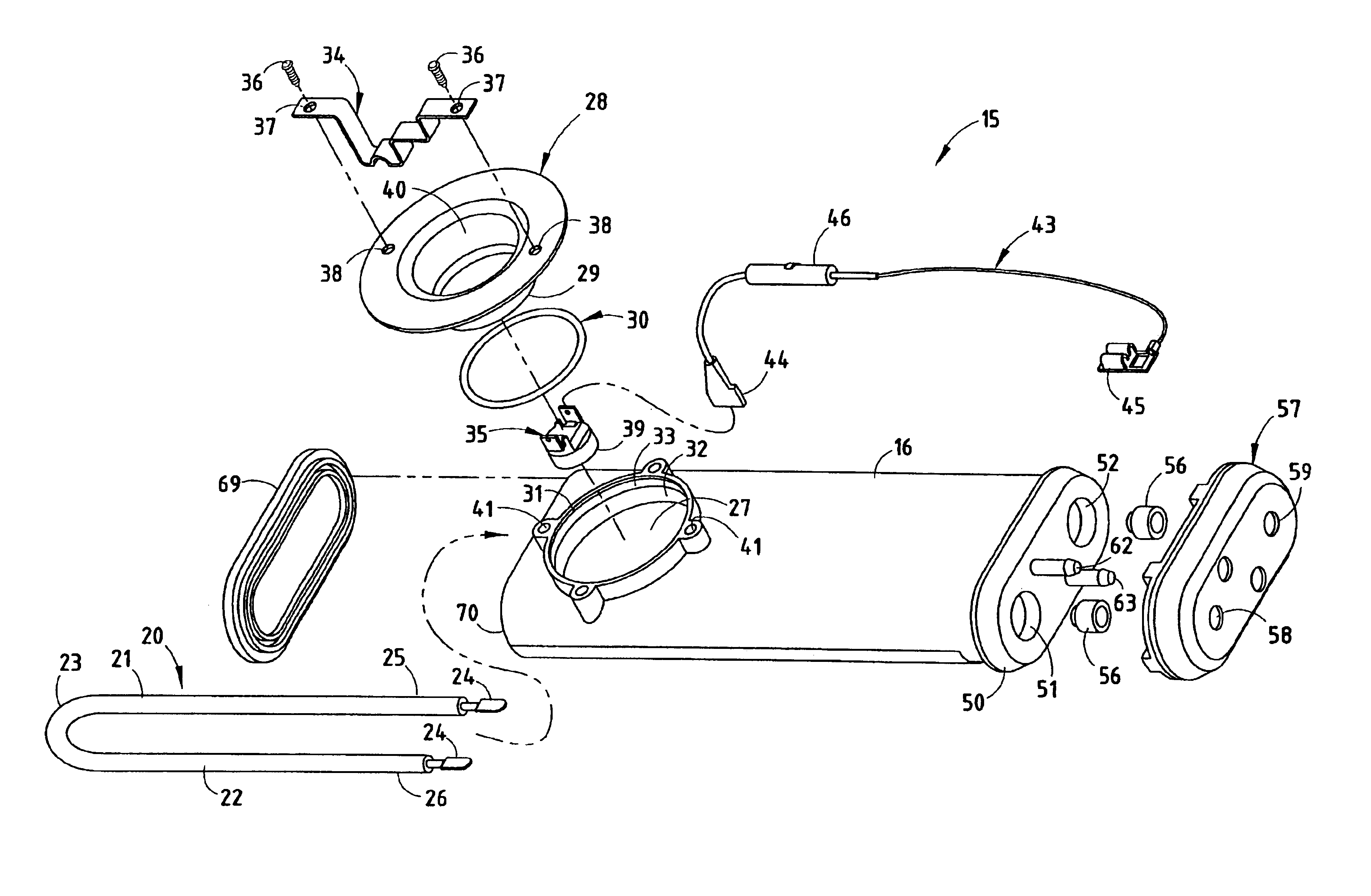
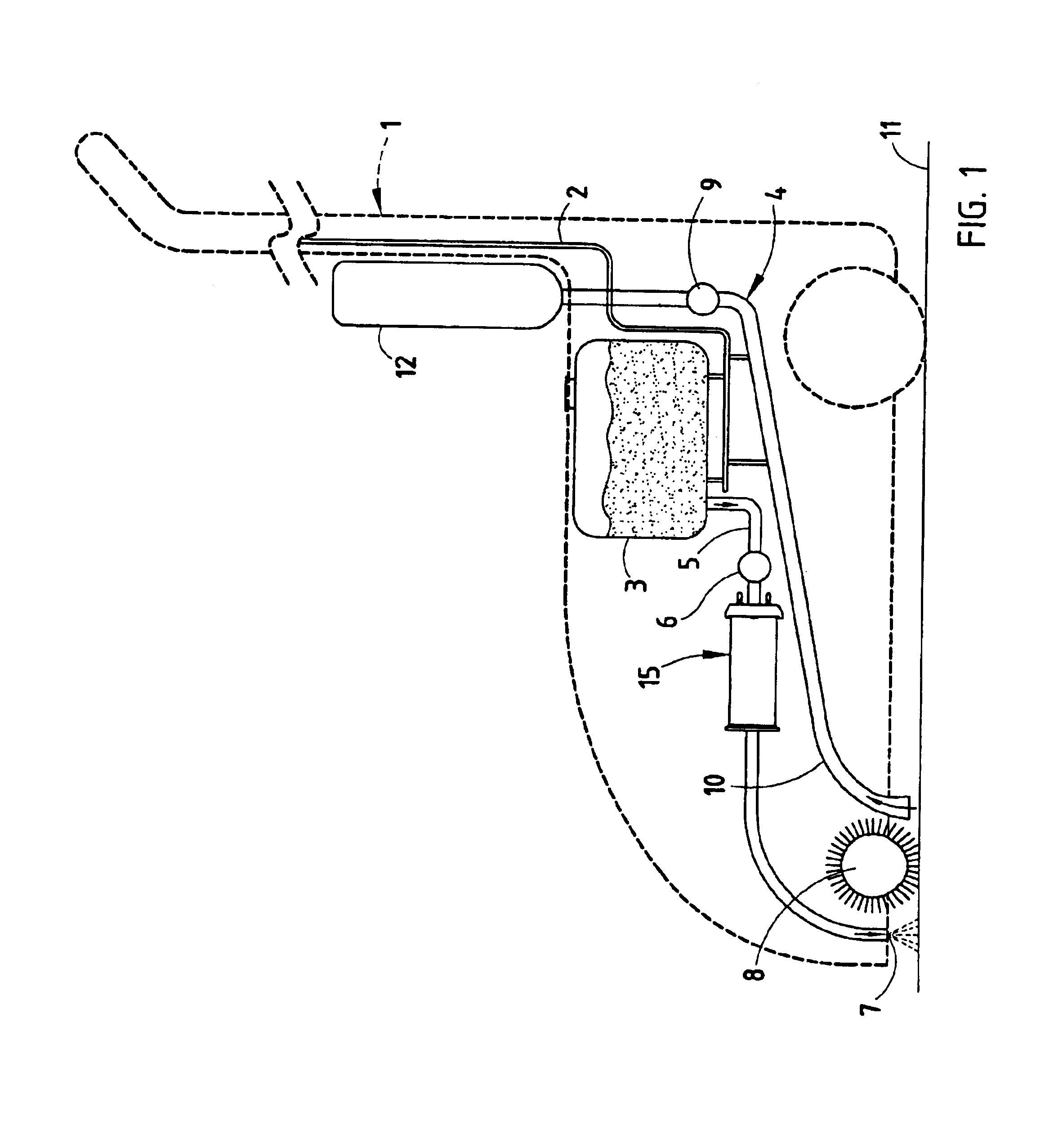
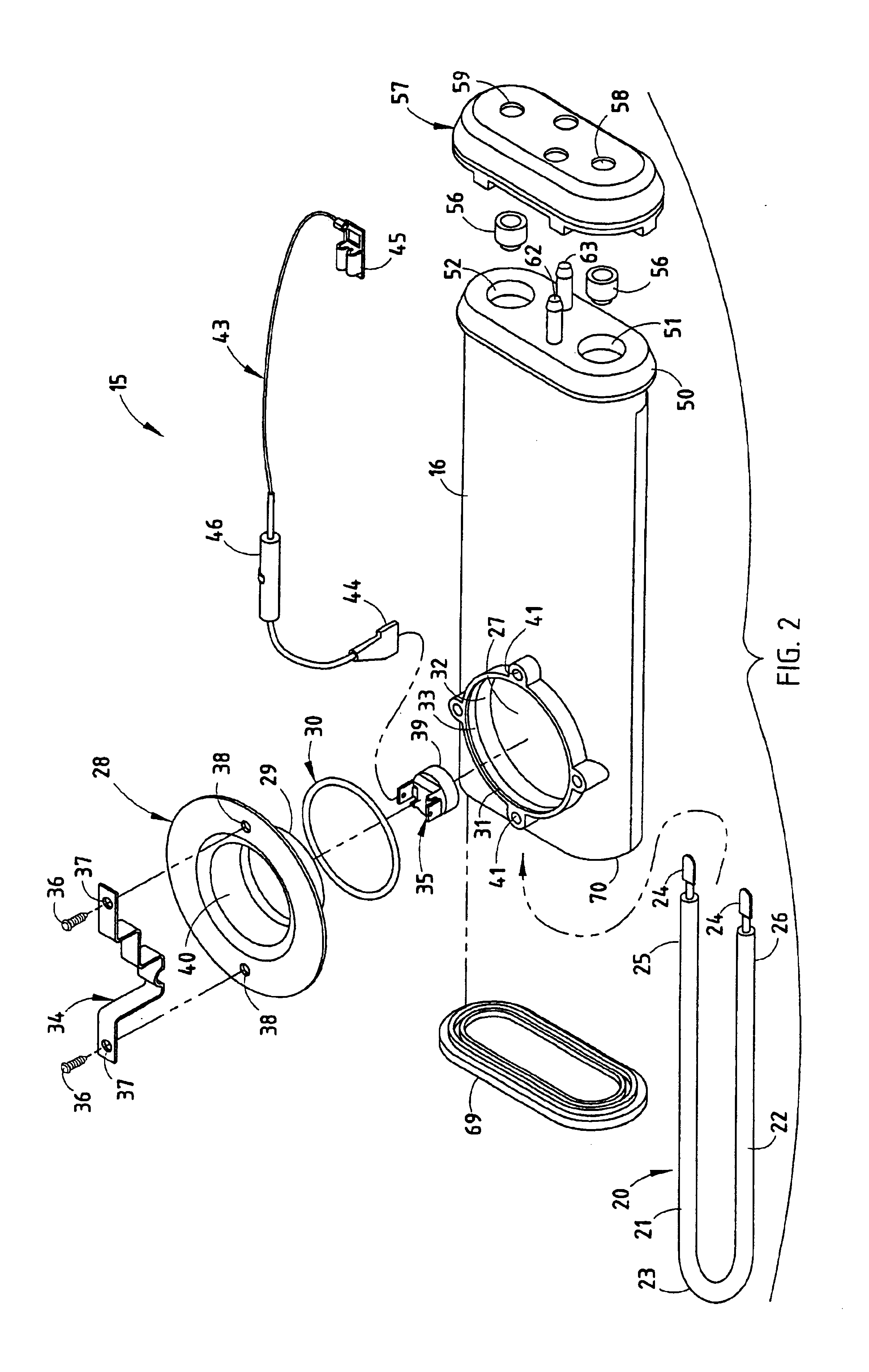
[0012]With reference to FIG. 1, a vacuum cleaner 1 generally includes a frame 2, a fluid reservoir 3, and a vacuum system 4. A fluid conduit assembly 5 includes a pump 6 that deposits fluid 7 fro...


PUM


Abstract

A heater for fluids including a housing made of a non-metallic material and having an internal cavity. The housing has an inlet and an outlet, each of which are in fluid communication with the internal cavity. An elongated electrical heating element is disposed within the cavity for heating fluid flowing through the cavity. The heating element has a generally circular cross-sectional shape and has a U-shaped portion disposed in the cavity. The electrical heating element has electrical connectors at opposite ends extending through the housing. The electrical heating element has a titanium outer surface.

Description

CROSS-REFERENCE TO RELATED APPLICATIONS[0001]The present application is a continuation-in-part of U.S. application Ser. No. 09 / 827,232, filed Apr. 5, 2001, the entire contents of which are incorporated by reference.BACKGROUND OF THE INVENTION[0002]Various vacuum cleaners have been developed that include a reservoir that holds cleaning fluid. The cleaning fluid is heated and deposited on the floor surface to be cleaned where it contacts a rotating brush of the vacuum cleaner. The cleaning fluid, dirt, and other material is then vacuumed from the floor surface. Heaters used for such vacuum cleaners are exposed to a harsh environment due to the caustic nature of the cleaning solution that flows through the heater, such that the heating elements may corrode or otherwise degrade. Also, such heaters are prone to lime buildup on the heating element that may reduce the effectiveness of the heater.SUMMARY OF THE INVENTION[0003]One aspect of the present invention is a heater for fluids includ...

Claims


Application Information

Patent Timeline
IPC IPC(8): H05B3/54H05B3/78H05B3/42H05B3/48F24H1/10A47L11/34
CPCA47L11/34A47L11/4041A47L11/4086F24H1/102H05B3/44H05B3/48H05B3/54H05B3/78H05B3/82
Inventor THWEATT, JR., CARLISLE
Owner BLUE DESERT INT INC
Why Eureka
Try Eureka