Rotating operating handle for vacuum cleaner

a technology of rotating operating handle and vacuum cleaner, which is applied in the direction of cleaning filter means, cleaning equipment, cable arrangements between relatively moving parts, etc., can solve the problems of inadvertent tipping, and achieve the effect of preventing inadvertent tipping preventing tipping over of floor care cleaning equipmen

Inactive Publication Date: 2005-09-13
PANASONIC OF NORTH AMERICA
View PDF13 Cites 47 Cited by
  • Summary
  • Abstract
  • Description
  • Claims
  • Application Information

AI Technical Summary

Benefits of technology

[0012]The pivotal axis A of the control handle is spaced a distance D1 from the bottom of the floor cleaning apparatus and the operating handle includes an end or stabilizer spaced a distance D2 from the axis A wherein D2 is less than D1 by about 0.5 to about 2.0 cm. Thus, the tip or stabilizer at the end of the control handle is positioned adjacent to the ground when the control handle assembly is in the storage position. In this position the tip or stabilizer will quickly engage the ground and prevent the tipping of the floor cleaning apparatus rearward.
[0013]In accordance with yet another aspect of the present invention a method is provided for preventing the inadvertent tipping of a floor care cleaning apparatus. The method includes the steps of providing a control handle assembly for the floor care cleaning apparatus that is displaceable between operating and storage positions. The method also includes the step of configuring the handle so that a portion thereof is adjacent the floor when the control handle is in the storage position whereby engagement of the portion with the floor prevents tipping over of the floor care cleaning apparatus. This is a particularly useful feature as it stabilizes the upright vacuum cleaner when the operator is using the wand and tool attachments during cleaning.

Problems solved by technology

Since many vacuum cleaners are stored in closets when not in use long coats and other items may be drug across the handle and result in inadvertent tipping.

Method used


Image

  • Rotating operating handle for vacuum cleaner
  • Rotating operating handle for vacuum cleaner
  • Rotating operating handle for vacuum cleaner

Examples


Embodiment Construction

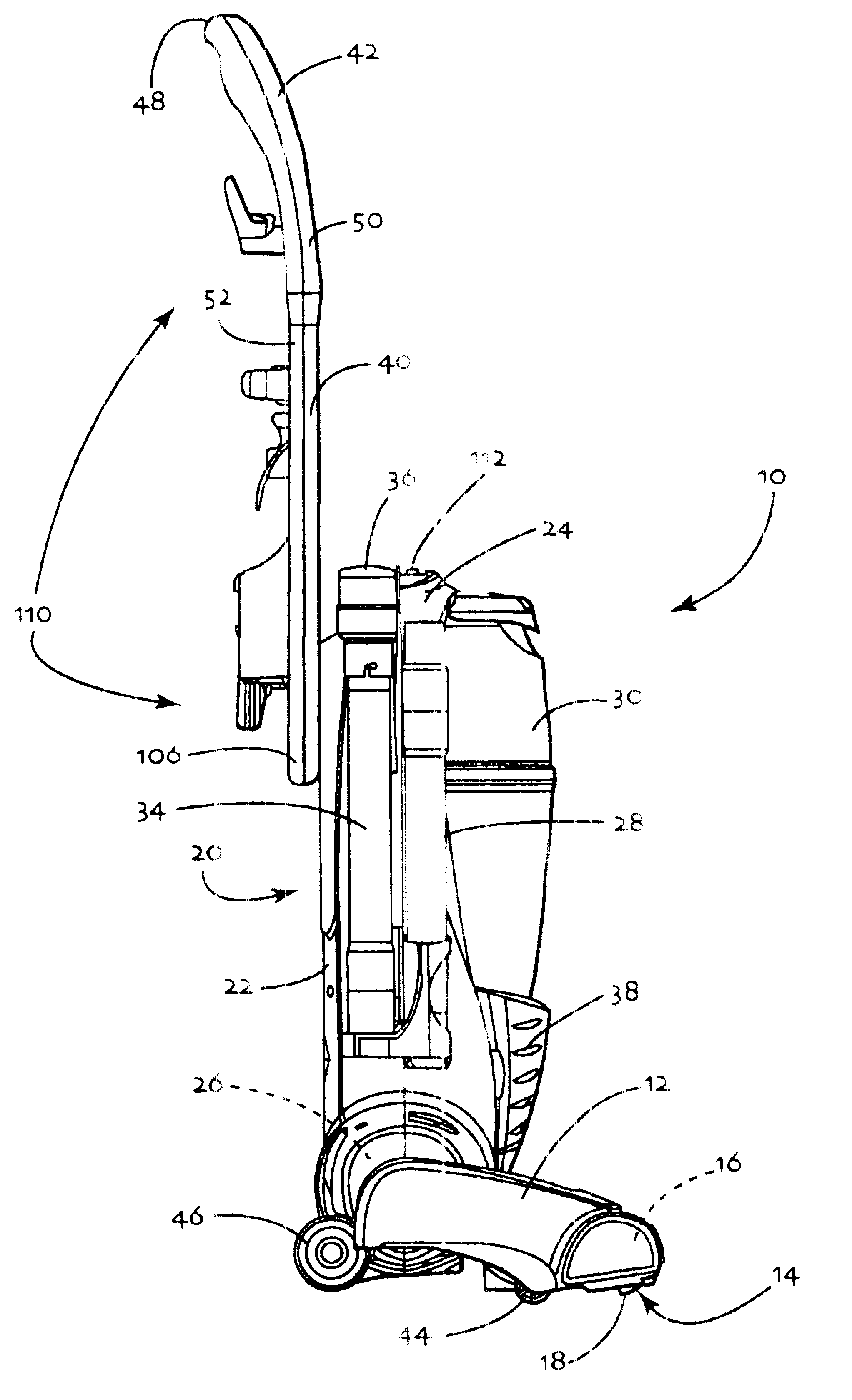
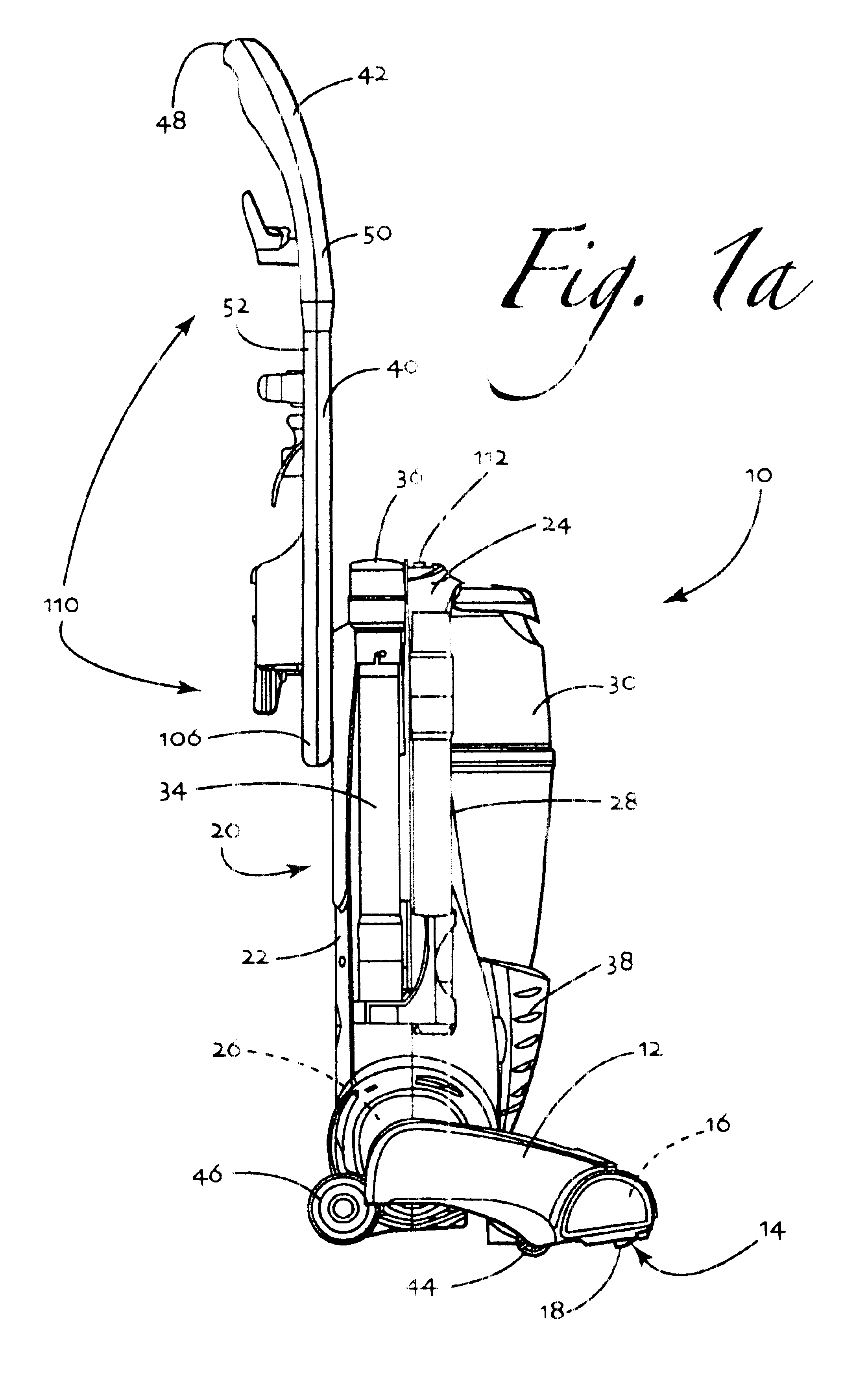
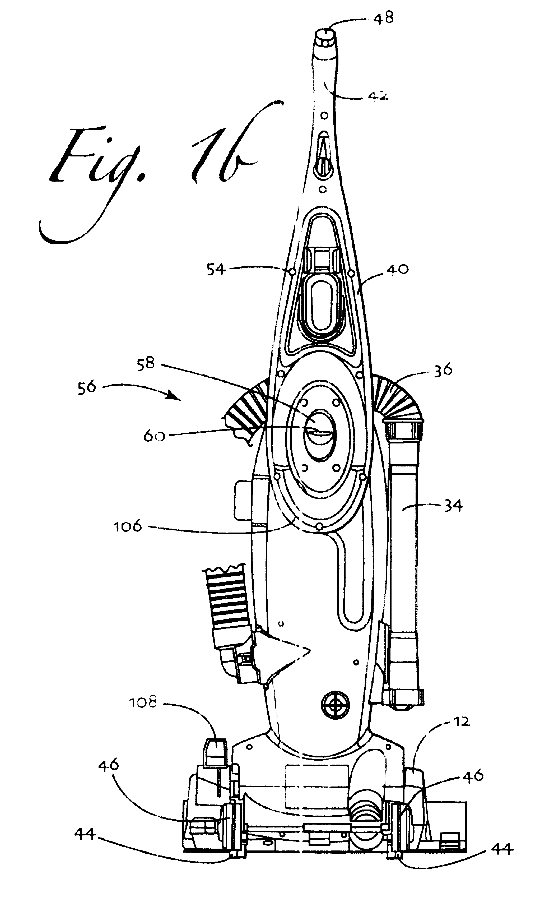
[0028]Reference is now made to FIGS. 1a and 1b illustrating the floor cleaning apparatus 10 of the present invention in the form of an upright vacuum cleaner. The apparatus 10 includes a nozzle assembly 12 that includes an intake opening 14. The nozzle assembly 12 also houses a rotary agitator 16 in the intake opening 14. The rotary agitator 16 may include tufts of bristles 18 or other cleaning structures such as wipers, beater bars and brushes for brushing and beating dirt from the nap of the underlying rug or carpet to be cleaned.

[0029]The apparatus 10 further includes a canister assembly, generally designated by reference numeral 20. The canister assembly 20 is pivotally connected to the nozzle assembly 12. The canister assembly 20 includes a first housing section 22 and a second, mating housing section 24. A suction generator 26, including a cooperating fan and drive motor, is housed in a compartment within the canister assembly 20. Additionally, the canister assembly 20 include...


PUM


Abstract

A floor cleaning apparatus includes a nozzle assembly and a canister assembly connected to the nozzle assembly. A suction generator and a dirt collection vessel are carried by the nozzle assembly or the canister assembly. In addition, the vacuum cleaner includes a control handle displaceable between operating and storage positions. A stabilizer on the handle is provided adjacent the floor in the storage position. Engagement of the stabilizer with the floor prevents the vacuum cleaner from inadvertently tipping over rearwardly.

Description

[0001]This application claims the benefit of U.S. Provisional Patent Application Ser. No. 60 / 465,705 filed on Apr. 26, 2003.TECHNICAL FIELD[0002]The present invention relates generally to the floor care equipment field and, more particularly, to a floor cleaning apparatus incorporating a control handle assembly that may be pivoted between an operating position in which the apparatus is manipulated to clean a floor and a storage position in which the handle stabilizes the apparatus by engaging the floor and preventing tipping.BACKGROUND OF THE INVENTION[0003]Upright vacuum cleaners of various shapes and designs have long been known in the art. Upright vacuum cleaners generally include a nozzle assembly including an intake opening, a canister assembly connected to the nozzle assembly, a suction generator for generating the negative air pressure to draw dirt and debris into the vacuum cleaner and a dirt collection vessel in the form of a bag or cup for collecting dirt for disposal.[000...

Claims


Application Information

Patent Timeline
Patent Type & Authority Patents(United States)
IPC IPC(8): A47L9/26A47L9/32A47L5/00A47LA47L9/00B08B7/00B08B9/20
CPCA47L9/325
Inventor SHANOR, MICHAEL J.MUDD, AMY N.
Owner PANASONIC OF NORTH AMERICA
Why Eureka
Try Eureka