Corrugated heat exchange element

Inactive Publication Date: 2005-09-13
MODINE MFG CO
View PDF24 Cites 16 Cited by
  • Summary
  • Abstract
  • Description
  • Claims
  • Application Information

AI Technical Summary

Benefits of technology

[0014]It is also considered advantageous that, in several groups of oblique structures, opposite slope angles of the oblique structures in one flank are provided from one group to the next group, in which, between the groups, the flanks are formed either without st

Problems solved by technology

Because the pattern is embossed flat in the entire metal strip, it is also located at the crests of the corrugated rib, so that the heat-conducti

Method used


Image

  • Corrugated heat exchange element
  • Corrugated heat exchange element
  • Corrugated heat exchange element

Examples


Embodiment Construction

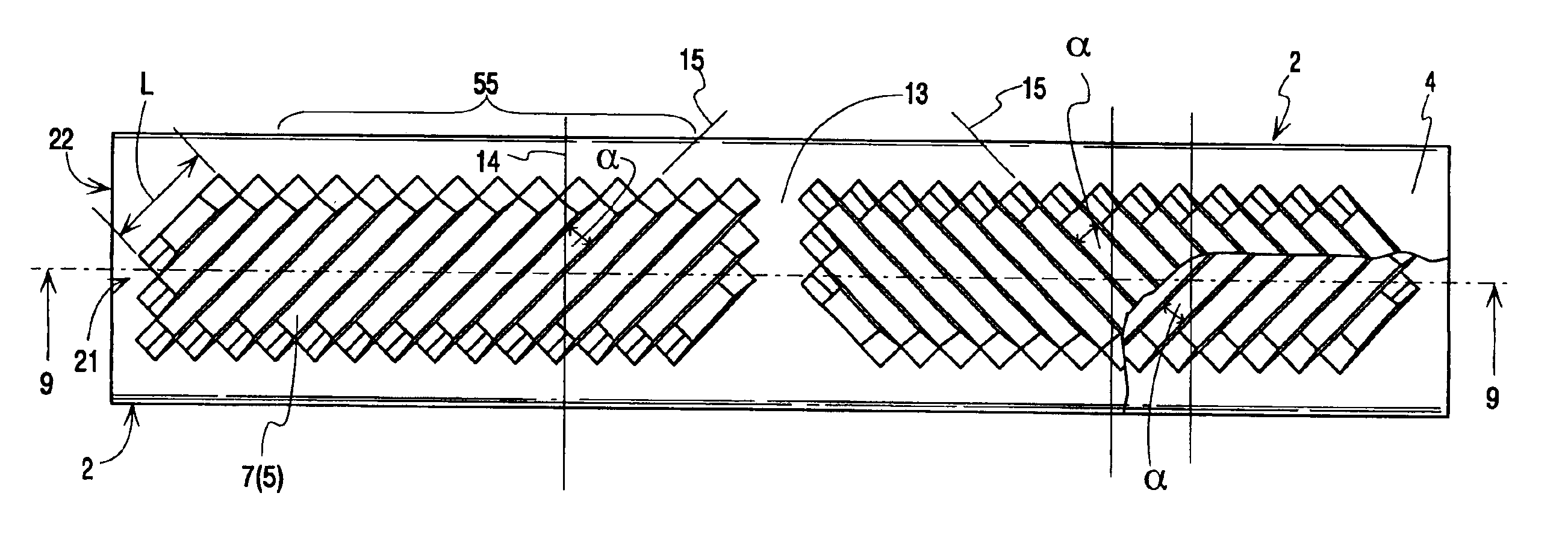
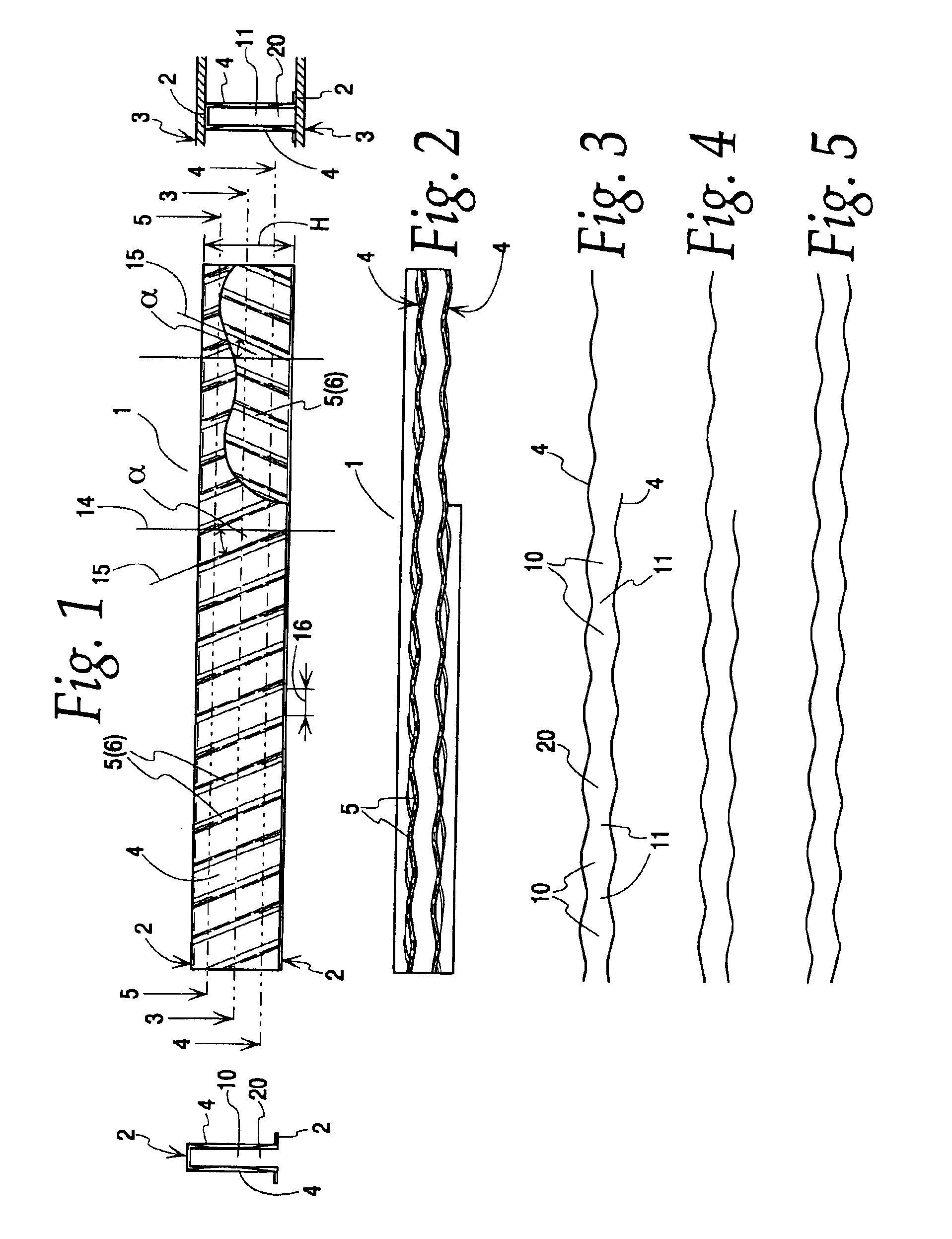
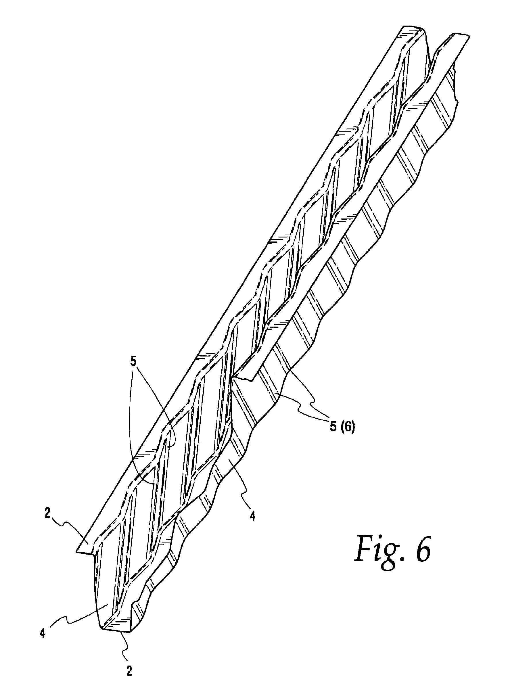
[0031]The depicted heat exchanger elements were produced from an aluminum strip. However, they could also be made of another appropriate metal. Production is carried out so that the structures 5 are initially embossed into the metal strip, structures 5 having a spacing from each other in the longitudinal direction of the strip. The size of the spacing corresponds in the practical example from FIGS. 1 to 6 to roughly the later crests 2 that are subsequently created by bending the strip in the transverse direction. Only a single corrugation was shown in the practical examples, but it is absolutely clear that the heat exchanger element 1 consists of an arbitrary number of corrugations, so that a first and second plane formed from the crests 2 are present.

[0032]The practical example from FIGS. 1 to 6 shows a sheet arranged as an internal insert in a channel of an oil cooler, which, however, was not shown in detail, because the alignment of sheets in heat exchangers made from stacked pla...


PUM


Abstract

The invention concerns a corrugated heat exchanger element (1) that can be produced from a metal strip and has a corrugation height (h) that lies between the crests (2) of the corrugations, in which the crests (2) form a first and second plane, consisting of several crests (2), at least some of the crests (2) of each plane being connected to the heat exchanger walls (3), and in which each crest (2) of the first plane is connected to the following crest (2) of the second plane by means of flanks (4), and a flow channel (20) is formed between adjacent flanks (4); structures (5), whose direction of alignment (15) in one flank (4) intersects the direction of alignment (15) in the following flank (4), are situated in the flanks (4). In order to improve the efficiency of heat exchange, it is proposed in a first variant according to the invention that the elements of structures (5) be beads (6) or corrugations or the like that provide the flow channel with alternating constrictions (11) and widenings (10), the adjacent flow channels (20) being essentially separated from each other in terms of flow. A second variant according to the invention proposes that the elements of the structures (5) be cuts (7) that connect the adjacent flow channels (20) together in terms of flow. A third variant prescribes that the elements of the structures be beads (6) or corrugations, in which cuts (7) lying in the direction of alignment (15) of the beads (6) or corrugations are arranged.

Description

FIELD OF THE INVENTION[0001]The invention concerns a corrugated heat exchange element.BACKGROUND OF THE INVENTION[0002]Corrugated heat exchange elements in the present sense are the so-called corrugated ribs that are inserted in air-cooled radiators between the flat tubes arranged in a row, in order to guarantee heat exchange between the medium in the flat tubes and the cooling air flowing through the corrugated ribs. The mentioned heat exchanger walls are the broad sides of the flat tubes in this case. The crests are designed arc-like.[0003]Other corrugated heat exchange elements are often referred to as sheets, or also as internal inserts, and are situated within the tubes or in channels formed by plates, for example, in plate heat exchangers that are encountered as oil coolers or the like. In such cases, the heat exchanger walls are the individual plates stacked one in the other. The crests are generally bent in a U-shape.[0004]The heat exchanger elements (corrugated ribs) define...

Claims


Application Information

Patent Timeline
IPC IPC(8): F28F1/12F28F3/00F28F3/02F28F13/08
CPCF28F1/128F28F3/025F28F13/08F28F13/12
Inventor NIES, JENS
Owner MODINE MFG CO
Why Eureka
Try Eureka