Light shielding flange

Inactive Publication Date: 2005-09-13
KONICA CORP
View PDF4 Cites 0 Cited by
  • Summary
  • Abstract
  • Description
  • Claims
  • Application Information

AI Technical Summary

Benefits of technology

[0021]The present invention was achieved in view of the above-described conditions, and its objective is to provide a thin type light shielding flange member, produced by injection molding method, wherein the hollow cylindrical boss section of the light shielding flange member is fixed into the hollow cylindrical inner section of the core without using supplementary parts, the inner shaft of the magazine is fixed without loosening and is easily removed from the inner side of hollow section of the hollow cylindrical boss section of the light shielding flange member, the production cost is inexpensive, and the production can be stably achieved.

Problems solved by technology

However, for recycling after use, the vinyl tape must be removed, and further, it is troublesome to wind the tape onto the outer periphery surface of the hollow cylindrical boss section, which are drawbacks.
Concerning the functions shown in (2) and (3), they are processed in such a way that the light shielding flange member is made by a vacuum molding or a pneumatic molding method having higher dimensional accuracy, but at lower productivity and higher cost, which are also drawbacks.
However, though production cost by the injection molding method is more favorable than production cost by the vacuum molding or pneumatic molding method, the thin type light shielding flange member disclosed in TOKKAIHEI 8-62783 is not sufficient to counter the above-described functions (1)-(3) which are required of the light shielding flange member, because of the following reasons.
(1) Since the thickness of the section where the rib is provided on the hollow cylindrical boss section is different from the thickness where there is no rib, a change of thickness results during the injection molding process, and thereby the thickness of the hollow cylindrical boss section is not uniform, and further, the form of the produced hollow cylindrical boss sections is also not uniform.
When such light shielding flange member is inserted into the hollow cylindrical section of the core of the rolled type photosensitive material, the connection between the hollow cylindrical boss section and the core is not secure, and thereby they may become separated, during the production of the ambient light loadable package.
(2) Since the thickness of a section where a rib is provided on the hollow cylindrical boss section is different from the thickness of a section where there is no rib, when the inner shaft of the magazine is inserted into a hollow section of the light shielding flange member, the hollow cylindrical boss section rarely expands uniformly, resulting in abnormal setting of the ambient light loadable package into the magazine.
(4) When an unstable supply of resin occurs during injection molding, it is very difficult to obtain uniform flatness of flange section.
If such a flange is used for packaging of the photosensitive material, the light may enter either or both side surfaces of the rolled photosensitive material, resulting in an ineffective light shield.

Method used


Image

  • Light shielding flange
  • Light shielding flange
  • Light shielding flange

Examples


Embodiment Construction

[0036]The preferred embodiments of the present invention will be described while referring to FIGS. 1-4, however, this invention is not limited to these embodiments.

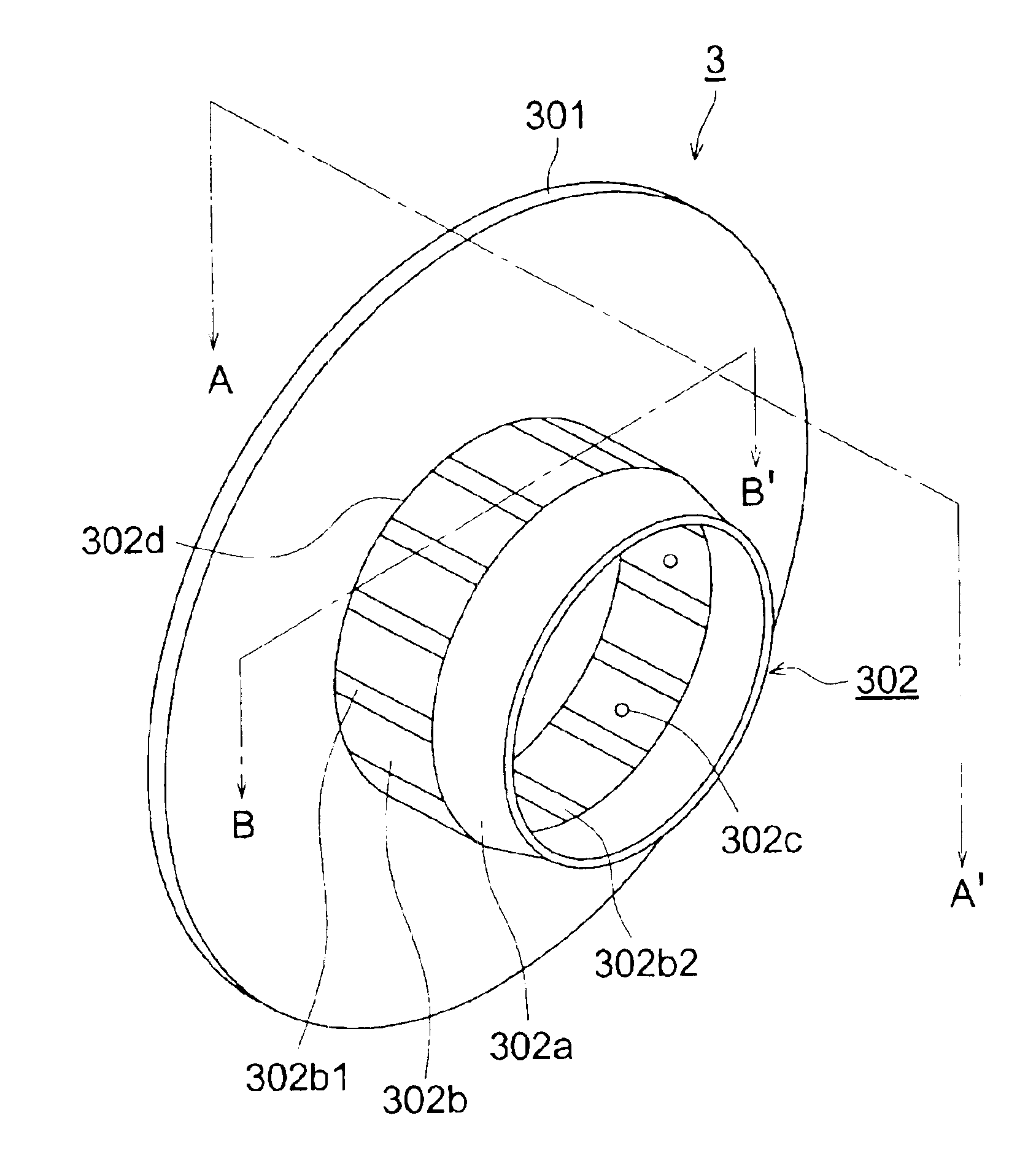
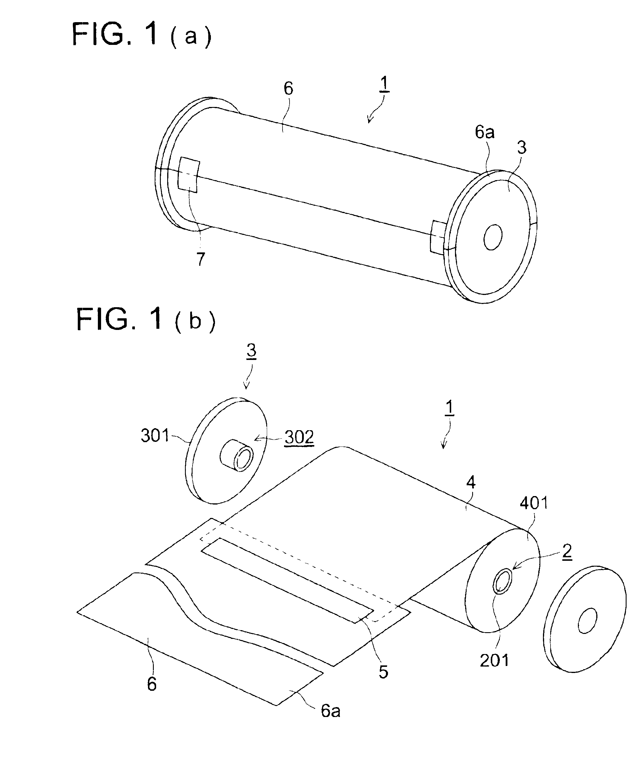
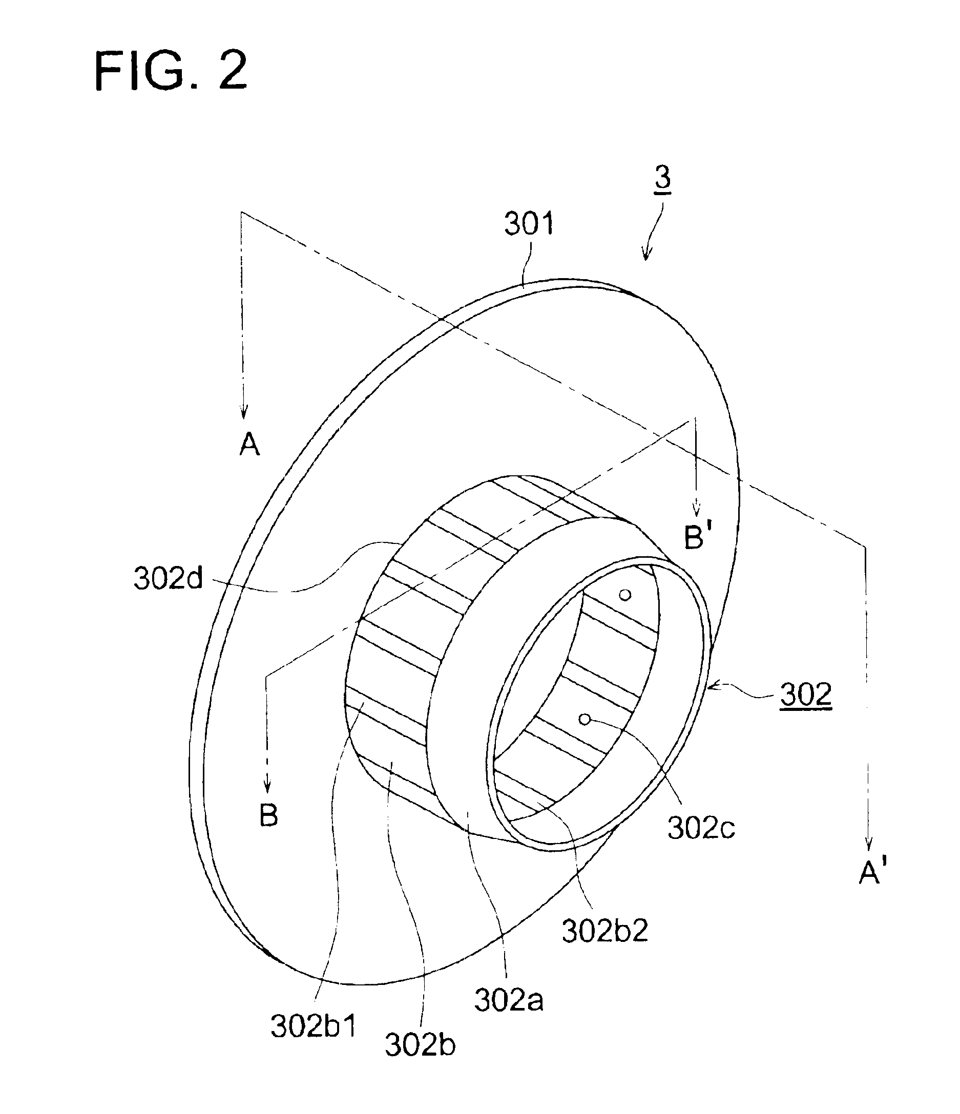
[0037]FIGS. 1(a) and 1(b) are schematic perspective views showing an example of the conformation of the ambient light loadable package of a rolled type photosensitive material. In FIG. 1(b), numeral 1 shows the ambient light loadable packaged photosensitive material wherein light shielding flange members 3 are fitted onto both ends of rolled type photosensitive material 4 wound around hollow cylindrical core 2, and wherein the rolled type photosensitive material 4 is light tight by use of light shielding leader 6, which is wider than rolled type photosensitive material 4 and is spliced by adhesive tape 5 onto the end of rolled type photosensitive material 4.

[0038]Since ambient light loadable packaged photosensitive material 1 is loaded into a magazine in ambient light, light shielding is very important. Therefore, in ord...


PUM


Abstract

Paired light shielding flange members, each having:a hollow cylindrical boss section to be inserted into a core around which a photosensitive material has been wound, wherein a plurality of rip sections are formed on the exterior surface of the cylindrical boss section parallel with an axis of the boss section, and an interior surface portion of rib is grooved in parallel with the axis of the hollow cylindrically boss section, anda flange section, integrated concentrically with the hollow cylindrical boss section, to prevent the edge of photosensitive material from being exposed to light.

Description

BACKGROUND OF THE INVENTION[0001]The present invention relates to paired light shielding flange members which are fitted into both ends of a hollow cylindrical core on which a rolled type photosensitive material has been wound.[0002]Hitherto, rolled type photosensitive materials have been packed to conform to so-called ambient light loadable packages. Ambient light loadable packages are structured in such way that, a wide and long photosensitive material is rolled up on a hollow cylindrical core, and light shielding flange members are fitted into both ends of the core, after a light shielding leader, which is wider than the rolled-up photosensitive material, is adhered to the end of the rolled-up photosensitive material, after which the light shielding leader is wound up onto the rolled-up photosensitive material, so that the peripheral sections of the light shielding flange members, fitted into both ends of the core, are covered by the light shielding leader, resulting in light shi...

Claims


Application Information

Patent Timeline
IPC IPC(8): G03C3/00G03G21/00
CPCG03C3/00Y10T428/218Y10T428/139
Inventor KOBAYASHI, HAJIMEIKARIYA, TOSHIYUKINAGASAKI, MITSURU
Owner KONICA CORP
Why Eureka
Try Eureka