
Automatic dispenser for underground sprinkler-systems

a technology of automatic dispensers and sprinklers, applied in the direction of liquid transfer devices, transportation and packaging, packaging, etc., can solve the problem of not being able to dispense fertilizer or other enhancements in balanced and measured amounts to different zones of operation

Inactive Publication Date: 2005-09-13
WALTER DAMIAN
View PDF5 Cites 4 Cited by
  • Summary
  • Abstract
  • Description
  • Claims
  • Application Information

AI Technical Summary

Benefits of technology

"The invention is an automatic fertilizer that can be used with a sprinkler system. It is placed between the backflow check valve and the zone valves of the system. The fertilizer is dispersed into a tank chamber below a discharge tray, which then distributes it to the appropriate sprinkler system zone. The discharge tray has multiple chambers based on the number of zones in the system. The chambers can hold various capacities based on the area covered by each zone. The discharge tray automatically moves as the sprinkler system changes from zone to zone. The unit has an access from the top to the discharge tray for filling chambers with fertilizer material. The invention aims to provide an automatic dispenser for underground sprinkler systems that can dispense fertilizers and other enhancements to multiple zones from a single location. It can be used in a variety of locations, such as gardens and lawns."

Problems solved by technology

Again, while this system works well of a single zone operation, there is no way to dispense fertilizer or other enhancements in balanced and measured amounts to different zones of operation.

Method used


Image

  • Automatic dispenser for underground sprinkler-systems
  • Automatic dispenser for underground sprinkler-systems
  • Automatic dispenser for underground sprinkler-systems

Examples


Embodiment Construction

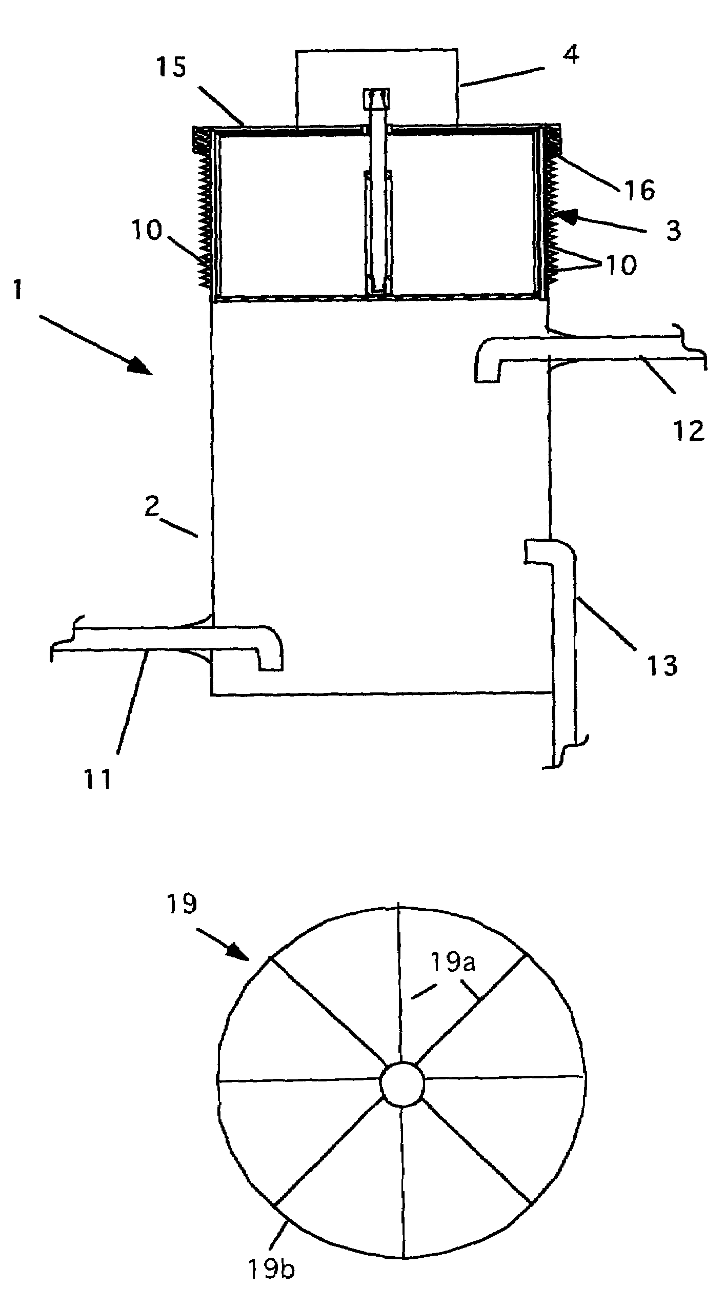
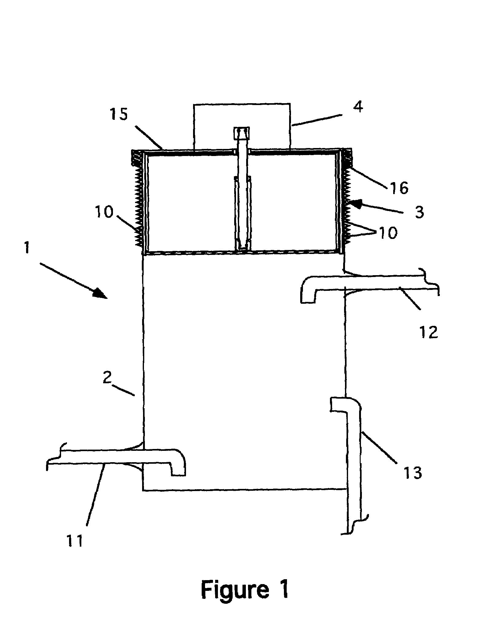
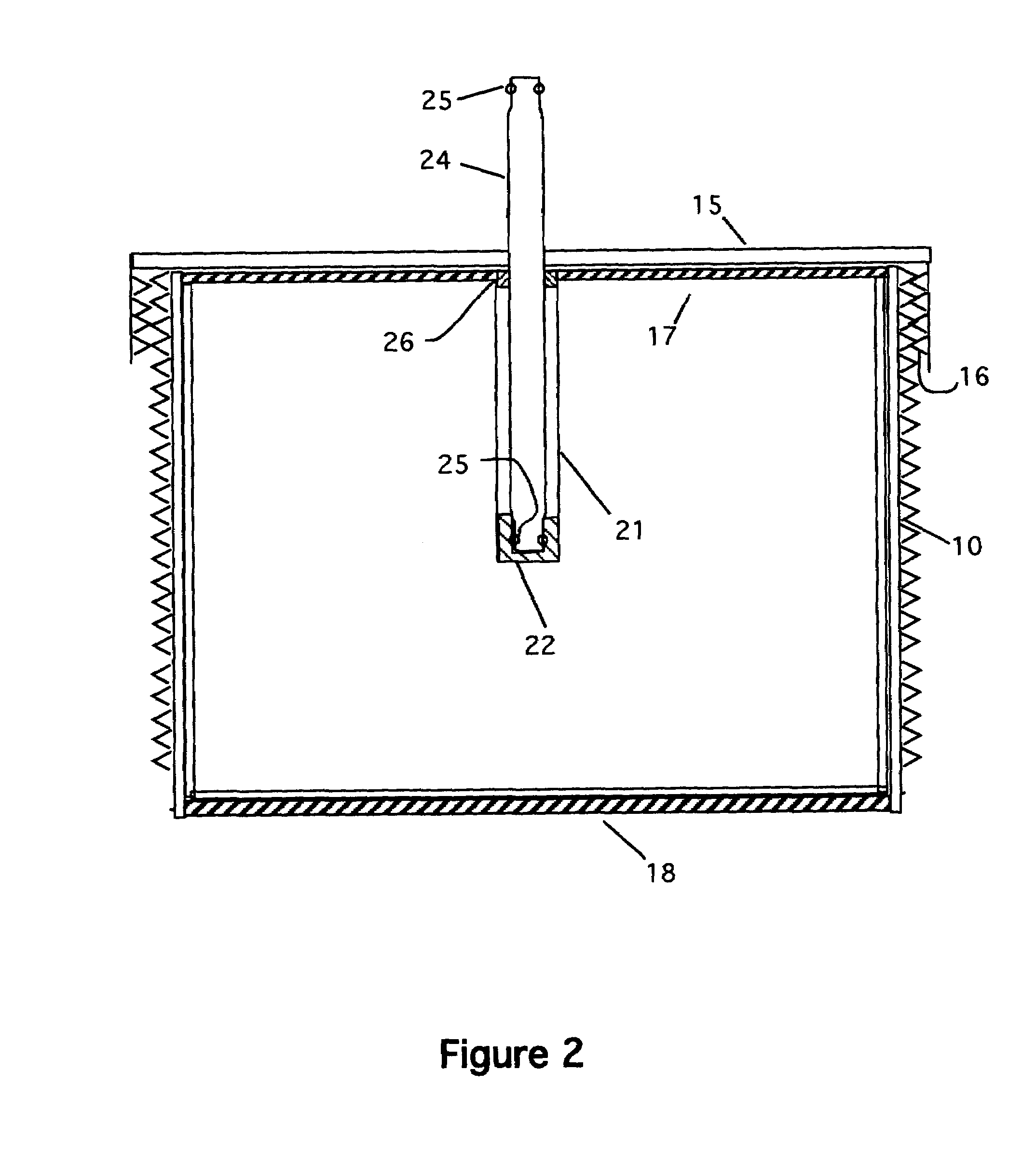
[0023]Referring now to FIG. 1, a cross-sectional view of the first embodiment 1 is shown. The major components of this embodiment are an agitation tank 2, a dispensing system 3 and a drive motor 4. The system 1 is typically placed in a sprinkler system between the backflow check valve (not shown) and the zone valves (see FIG. 9) of the sprinkler system. In this way, the unit 1 can service all the zones from one location.

[0024]The tank 2 has a number of threads 10 formed about the outside of the top of the tank. The threads 10 are used to secure the lid of the dispensing system 3, as discussed below. As an alternative, latches can be used instead of the threads. The tank 2 has an inlet pipe 11 and an outlet pipe 12. The inlet pipe is positioned near the bottom of the tank. For example, in the preferred embodiment, the inlet pipe is placed about ½ inch (12 mm) above the bottom of the tank to allow water to enter the tank at the bottom. The exit pipe is positioned at a point just below...


PUM


Abstract

An automatic fertilizer that is designed to be used with a yard / lawn / garden sprinkler system. This unit is placed before the zone valves of the sprinkler system. The unit is designed to disperse fertilizer into a tank chamber below a discharge tray. The fertilizer dissolves in the water and is distributed / dispersed to the appropriate sprinkler system zone. The discharge tray has multiple chambers based on the number of zones in the sprinkler system. The chambers in the discharge tray can hold various capacities based on the area covered by each zone within the sprinkler system. The discharge tray turns to dispense the fertilizer as the sprinkler system changes from zone to zone. The discharge tray is automatically moved. The chambers are manually refilled based on the frequency of yard fertilization. The unit has an access from the top to the discharge tray for filling chambers with fertilizer material.

Description

CROSS REFERENCE TO RELATED APPLICATIONS[0001]Not ApplicableSTATEMENT REGARDING FEDERALLY SPONSORED RESEARCH AND DEVELOPMENT[0002]Not ApplicableBACKGROUND OF THE INVENTION[0003]1. Field of the Invention[0004]This invention relates to automatic fertilizer systems and particularly to automatic fertilizer systems used with automatic sprinkler systems.[0005]2. Description of the Prior Art[0006]Underground sprinkler systems have been used for many years to water lawns. Typically, these systems use buried flexible PVC pipe to feed a number of sprinkler heads placed about a lawn. Alternatively, perforated pipe may be substituted for the sprinkler heads. In this case, the perforations disburse water into the ground directly watering a lawn.[0007]One advantage of these systems is that fertilizer and other enhancements can be added directly to the water stream, thereby spreading these enhancements over the entire lawn during the watering process. One example of such a device is found in U.S. P...

Claims


Application Information

Patent Timeline
Patent Type & Authority Patents(United States)
IPC IPC(8): B05B7/24B05B7/26B65G47/34B67D5/56B67D7/74
CPCA01G25/00
Inventor WALTER, DAMIAN
Owner WALTER DAMIAN
Learn More