Valve Assembly with Retainer

A technology of valve components and retaining rings, applied in the direction of lift valves, valve devices, engine components, etc.

Active Publication Date: 2020-11-10
VOLKSWAGEN AG
View PDF8 Cites 0 Cited by
  • Summary
  • Abstract
  • Description
  • Claims
  • Application Information

AI Technical Summary

Problems solved by technology

This results in so-called restrictions in terms of demoulding technology with regard to the opening of the valve unit and the geometry of the lifting tabs

Method used


Image

  • Valve Assembly with Retainer
  • Valve Assembly with Retainer
  • Valve Assembly with Retainer

Examples


Embodiment Construction

[0065] In the figures, identical or functionally identical elements are provided with the same reference signs. Furthermore, it should be noted that the illustrations in the figures are not necessarily drawn to correct scale.

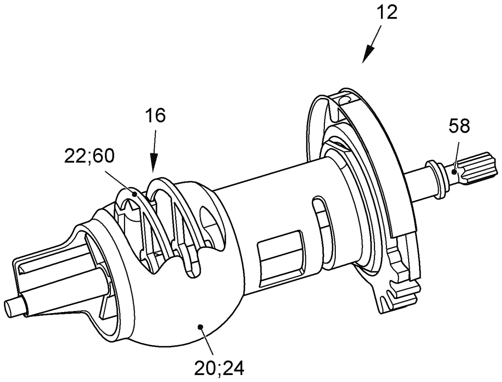
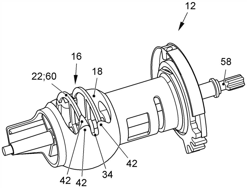
[0066] figure 1 An exploded view of the valve assembly 10 according to the invention is shown. The valve assembly 10 may in particular be a regulating valve for regulating a coolant circuit of an internal combustion engine. The valve assembly 10 has a valve unit 12 , a sealing element 14 and a retaining ring 16 . The valve unit 12 serves to guide fluid. Fluid can escape or enter at the opening 18 in the peripheral surface 20 of the valve unit 12 . In contrast, the sealing element 14 serves to seal the transition between the valve unit 12 and the fluid channel ( figure 1 not shown). A fluid channel is formed through the housing adjoining the sealing element. The transition is the area between the valve unit 12 and the fluid channel.

[0067] The ...


PUM


Abstract

The present invention relates to a valve assembly with a retainer, and more particularly to a valve assembly (10), particularly a regulating valve for regulating a coolant circuit of an internal combustion engine. The valve assembly (10) is provided with a valve unit (12) for directing fluid through an opening (18) and a sealing element (14) for sealing a transition between the valve unit (12) andthe fluid passage. Furthermore, the valve assembly (10) is provided with a retainer (16) for preventing the sealing element (14) from sinking into the opening (18) of the valve unit (12), wherein theretainer (16) is arranged in the valve unit (12). Furthermore, the retainer (16) has an exposed area (22) at the opening (18). The contour (24) of the valve unit (12) continues at the exposed area (22) of the retainer (16).

Description

technical field [0001] The present invention relates to a valve assembly. Background technique [0002] Conventional internal combustion engines usually have one or more coolant circuits (Kühlmittelkreislauf) for cooling, wherein the coolant can be routed, for example, through a first coolant path with a heat exchanger or through a second coolant circuit without a heat exchanger. coolant path. In order to regulate the amount of coolant to be guided through the different coolant paths, a valve arrangement, for example a rotary slide valve, is usually provided. The valve assembly has an adjustable valve unit (Ventilglied), for example a rotary slide, which in a first valve position releases the passage between the fluid inlet channel (Fluidzuführkanal) and the first fluid outlet channel (Fluidableitkanal), and In the second valve position, the passage between the fluid inlet channel and the second fluid outlet channel is released. Intermediate positions of the valve unit ar...

Claims


Application Information

Patent Timeline
Patent Type & Authority Patents(China)
IPC IPC(8): F16K1/34F16K1/36
CPCF16K1/34F16K1/36F16K5/0605F16K5/12
Inventor H.弗里斯
Owner VOLKSWAGEN AG
Why Eureka
Try Eureka