Shielding cage with improved EMI shielding gasket construction

a technology of shielding cage and gasket, which is applied in the construction details of electrical apparatus, coaxial cables/analogue cables, and coupling device connections. it can solve the problems of poor emi shielding, loose fitting chassis components, and poor electrical contacts of loose fitting chassis components

Active Publication Date: 2005-09-13
MOLEX INC
View PDF13 Cites 58 Cited by
  • Summary
  • Abstract
  • Description
  • Claims
  • Application Information

AI Technical Summary

Benefits of technology

[0010]Yet another object of the present invention is to provide a gasket for a shielding cage, the cage having multiple module-receiving bays, the cage having a plurality of engagement tabs being formed therewith and spaced apart thereon such that the engagement tabs are aligned with intersections of interior walls of the cage and exterior walls of the cage, the engagement tabs having an L-shaped configuration with a back portion and a clamping portion extending in a cantilevered fashion over exterior surfaces of the cage, the engagement tabs receiving a rigid backing plate in gaps formed between the clamping portions thereof and the cage exterior surfaces, the inner walls of the cage being aligned with the engagement tabs to provide structural rigidity to the tabs and to provide a support therefor that resists bending.

Problems solved by technology

Although prior art EMI-shielded cages provided some EMI suppression, they did not provide a means by which a chassis front panel can be well-grounded.
Loose-fitting chassis components provide poor electrical contacts.
Depending upon the power level and frequency of EMI, loose-fitting chassis components usually provide poor EMI shielding.
These modules are spaced apart widthwise on the circuit board and this arrangement takes up a large amount of space.

Method used


Image

  • Shielding cage with improved EMI shielding gasket construction
  • Shielding cage with improved EMI shielding gasket construction
  • Shielding cage with improved EMI shielding gasket construction

Examples


Embodiment Construction

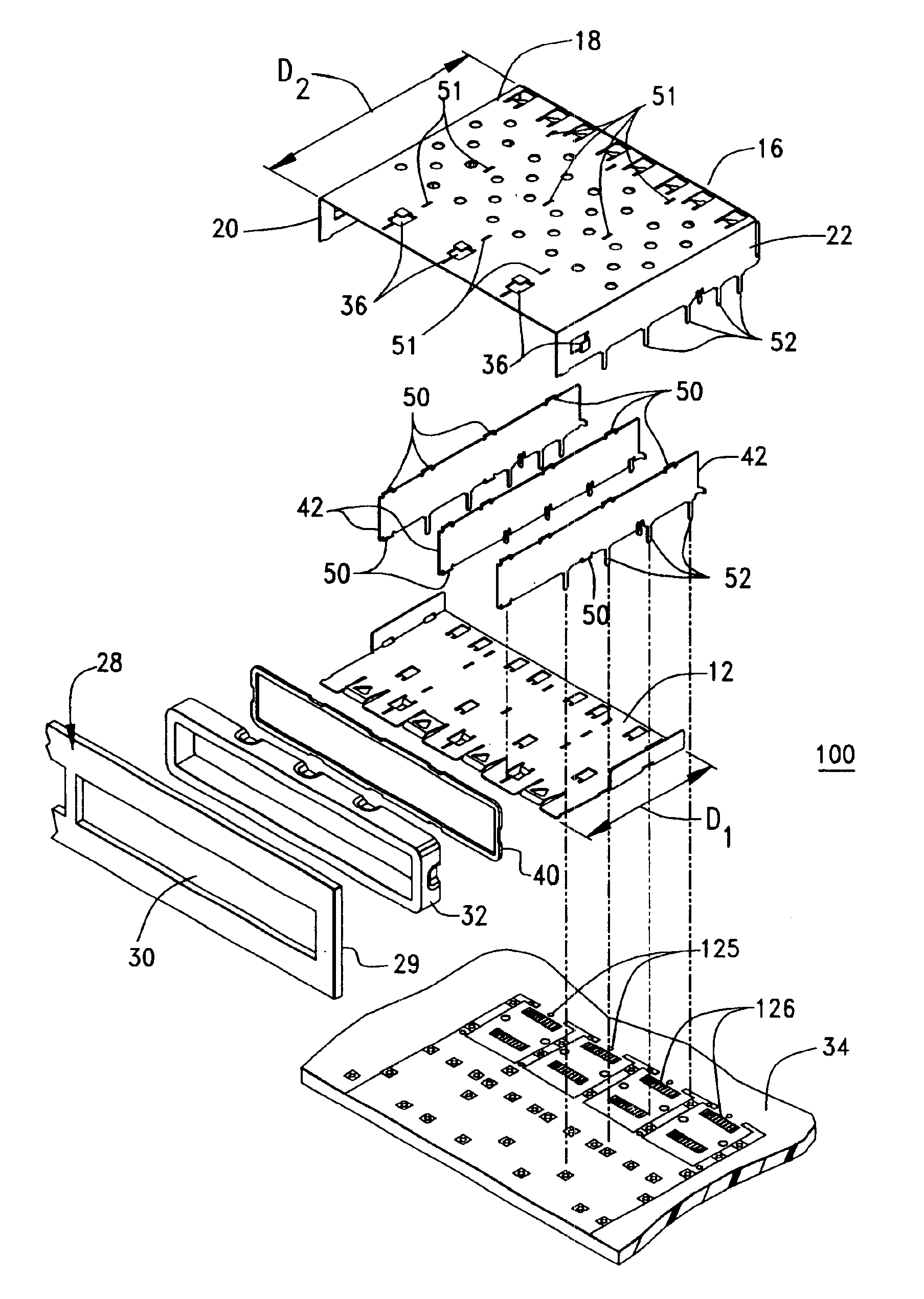
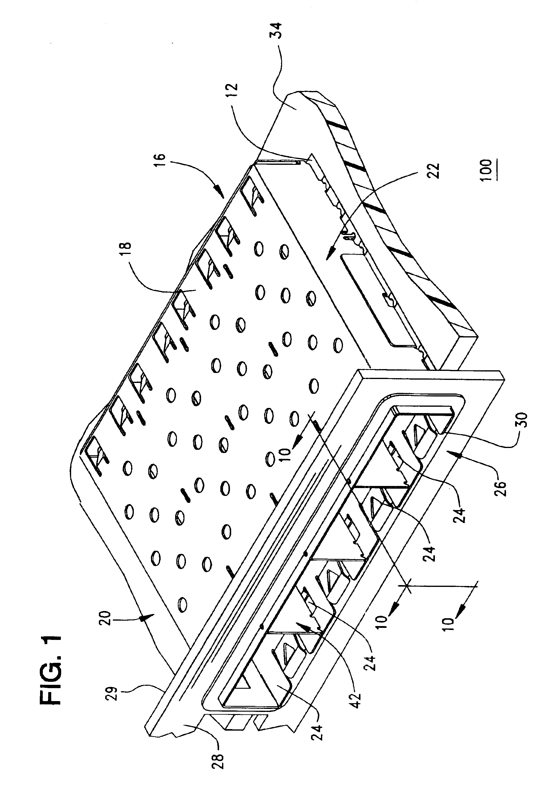
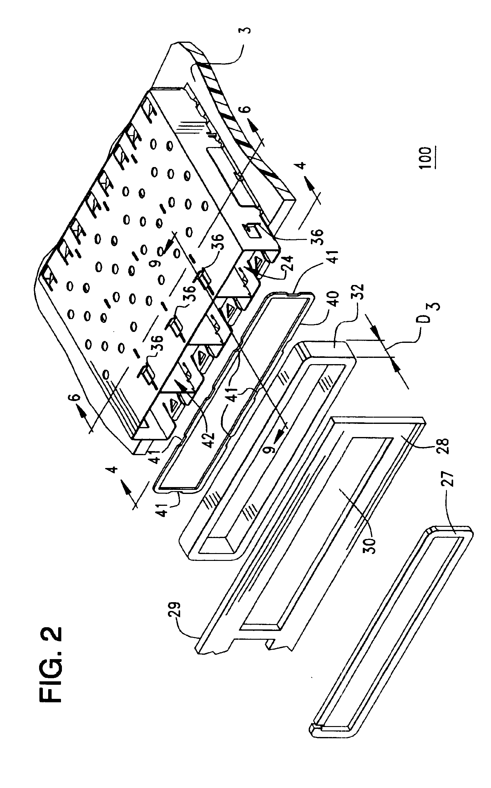
[0025]FIG. 1 shows a perspective view of an electromagnetic interference (EMI) shielding cage 100 for housing one or more electronic modules. Electronic modules are typically used to provide a connection between circuits on a circuit board 34 and another electronic device. These are used commonly in data transmission servers and routers. Such modules may include adapters that use a small circuit board to mate with a card edge connector mounted to the circuit board and held within the rear of the cage 100, or may include optical transceivers which permit the conversion of optical signals transmitted through fiber optic cables to electrical signals that are transmitted through circuits on the circuit board 34. The modules or adapters, are plugged into individual bays or receptacles mounted to the circuit board 34 and which have an opening that communicates with the exterior of the device, preferably through a panel 28 of the device. These metal cages 100 are used to shield the modules...


PUM

PropertyMeasurementUnit
electromagnetic interferenceaaaaaaaaaa
conductiveaaaaaaaaaa
electrically-conductiveaaaaaaaaaa

Abstract

An electromagnetic interference (EMI) shielding cage for an electronic module is comprised an electrically-conductive bottom, an electrically-conductive rear panel electrically coupled to said bottom, an electrically-conductive, elongated cover electrically coupled to said bottom and first and second side walls that are electrically and mechanically coupled to said bottom, said rear panel and said elongated cover. Numerous ground lugs, electrically coupled to at least one of: said bottom; rear panel; and first and second side walls provide an electrical pathway for EMI signals to a reference potential. An electrically-conductive, compressible gasket encircling the bottom, top and side walls provides an electrical connection to a front panel, providing additional EMI suppression. Gasket engagement tabs in the top and bottom provide electrical connection between the gasket and panels.

Description

REFERENCE TO RELATED APPLICATIONS[0001]This application claims priority from U.S. Provisional Patent Application No. 60 / 459,092, filed Mar. 31, 2003.BACKGROUND OF THE INVENTION[0002]The present invention relates generally to shielding cages used to shield electronic modules from electromagnetic interference, and more particularly to shielding cages with gaskets for shielding electromagnetic radiations emanating from the modules during operation thereof.[0003]In the prior art, electronic circuitry requiring shielding from electromagnetic interference (EMI) is often mounted into a sheet metal chassis, or housing, that suppresses EMI signals. Although prior art EMI-shielded cages provided some EMI suppression, they did not provide a means by which a chassis front panel can be well-grounded. Loose-fitting chassis components provide poor electrical contacts. Depending upon the power level and frequency of EMI, loose-fitting chassis components usually provide poor EMI shielding.[0004]In o...

Claims


Application Information

Patent Timeline
Patent Type & Authority Patents(United States)
IPC IPC(8): H01R13/658H01R12/00H01R12/16H05K9/00
CPCH01R13/65802H01R23/6873H05K9/0058H01R13/6584H01R13/659H01R13/6594
Inventor LLOYD, BRIAN KEITHDOYE, DENNIS LEE
Owner MOLEX INC
Why Eureka
Try Eureka