Electronic ballast for a discharge lamp

a technology of electronic ballast and discharge lamp, which is applied in the direction of sustainable manufacturing/processing, instruments, final product manufacturing, etc., can solve the problems of difficult compactness and easy installation in a limited space, and achieve the effect of reducing the number of overall components, reducing the number of discrete components, and stably supplied

Inactive Publication Date: 2005-09-13
MATSUSHITA ELECTRIC WORKS LTD
View PDF14 Cites 25 Cited by
  • Summary
  • Abstract
  • Description
  • Claims
  • Application Information

AI Technical Summary

Benefits of technology

[0021]The output transformer is preferred to include a first auxiliary winding which provides a driving voltage for energizing the control circuit, a second auxiliary winding which provides a detection output indicative of the high frequency output voltage for monitoring the operation of the discharge lamp, and a third winding which provides a preheat current to filaments of the discharge lamp. Thus, the output transformer alone can provide versatile functions, which reduces the number of the discrete components for the inverter, leading to a compact assembly of the ballast.
[0022]Preferably, the output transformer is a leakage transformer having a primary winding connected in circuit to flow a high frequency current, and a secondary winding which is magnetically coupled to the primary winding to induce the high frequency output voltage being applied to the discharge lamp. With the use of the output transformer of the leakage type, a leakage inductance can be best utilized as an oscillation inducing inductance for the inverter operation, requiring no additional separate inductance and therefore reducing the number of the overall components of the inverter for compact arrangement of the ballast. Further, the first auxiliary winding is coupled to the first auxiliary winding so as to provide the driving voltage for energizing the control circuit. Thus, the control circuit can be stably supplied with the energy irrespective of the operating condition of the discharge lamp. Also, the second auxiliary winding is coupled to the secondary winding so as to provide the detection output indicative of the high frequency output voltage such that the second auxiliary winding can provide the detection output reliable enough for detection of the operating condition of the discharge lamp.
[0023]The AC-DC converter includes a rectifier providing the rectified DC voltage. The control circuit is preferred to include a dropping resistor which is connected to the rectifier for deriving a DC voltage for energizing the control circuit at the time of starting the inverter. Thus, the dropping resistor is integrated into the control circuit to reduce the number of the discrete components.
[0024]Most preferably, the inverter is of a charge-pump type having a capacitor which is connected in a path of receiving an input current from said AC-DC converter and flowing the input current through an oscillating element of the inverter and through the switching element for restraining harmonics in the input current from the source AC voltage. With the use of the charge-pump type inverter, it is possible to restrain the harmonics of the input current from the source AC voltage and therefore improve power factor of the ballast without requiring any external harmonic filter, contributing to reduce the number of the circuit components for the inverter capable of suppressing the harmonics.
[0025]The ballast may include an adjusting means mounted on the circuit board to adjust output characteristics of the discharge lamp for operating the discharge lamp successfully even when the ballast is energized by the source AC voltage of different voltages, thereby enabling to operate the lamp consistently from the differing AC voltage sources with the use of the common ballast.
[0026]The adjustor means can operate to adjust a lamp start output power and a lamp operating output power fed to the discharge lamp respectively at the time of starting the lamp and during the steady-state operation of the lamp, thereby minimizing electrical stress applied to the electric components of the inverter and therefore giving reliability thereto, in addition to facilitating the circuit design of the inverter.

Problems solved by technology

Accordingly, the prior art ballast has an underlying problem in that it is difficult to be made compact for easy installation in a limited space when the ballast is equipped with the added function of controlling the operation of the discharge lamp based upon the detected operating condition thereof and includes the output transformer.

Method used


Image

  • Electronic ballast for a discharge lamp
  • Electronic ballast for a discharge lamp
  • Electronic ballast for a discharge lamp

Examples


Embodiment Construction

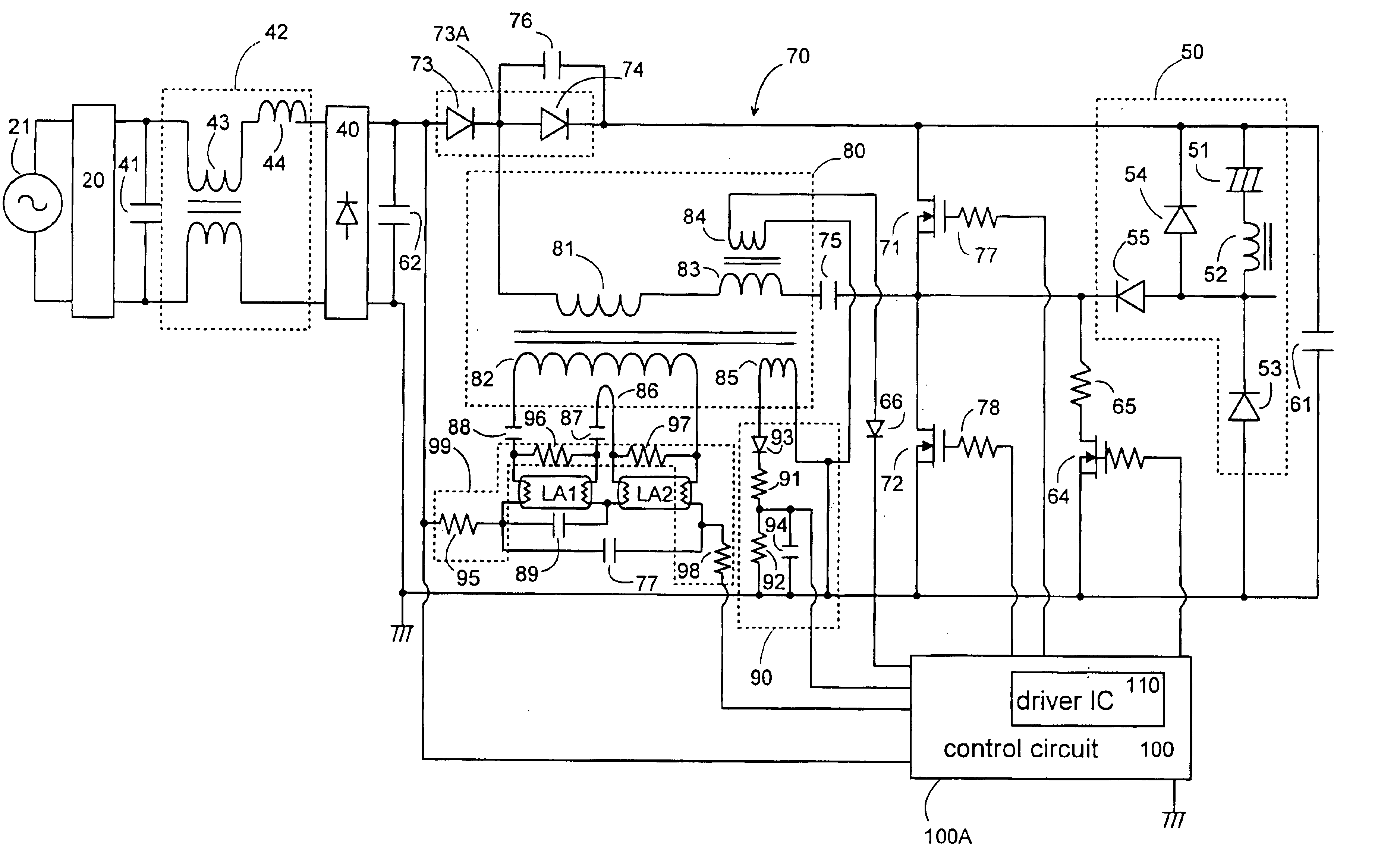
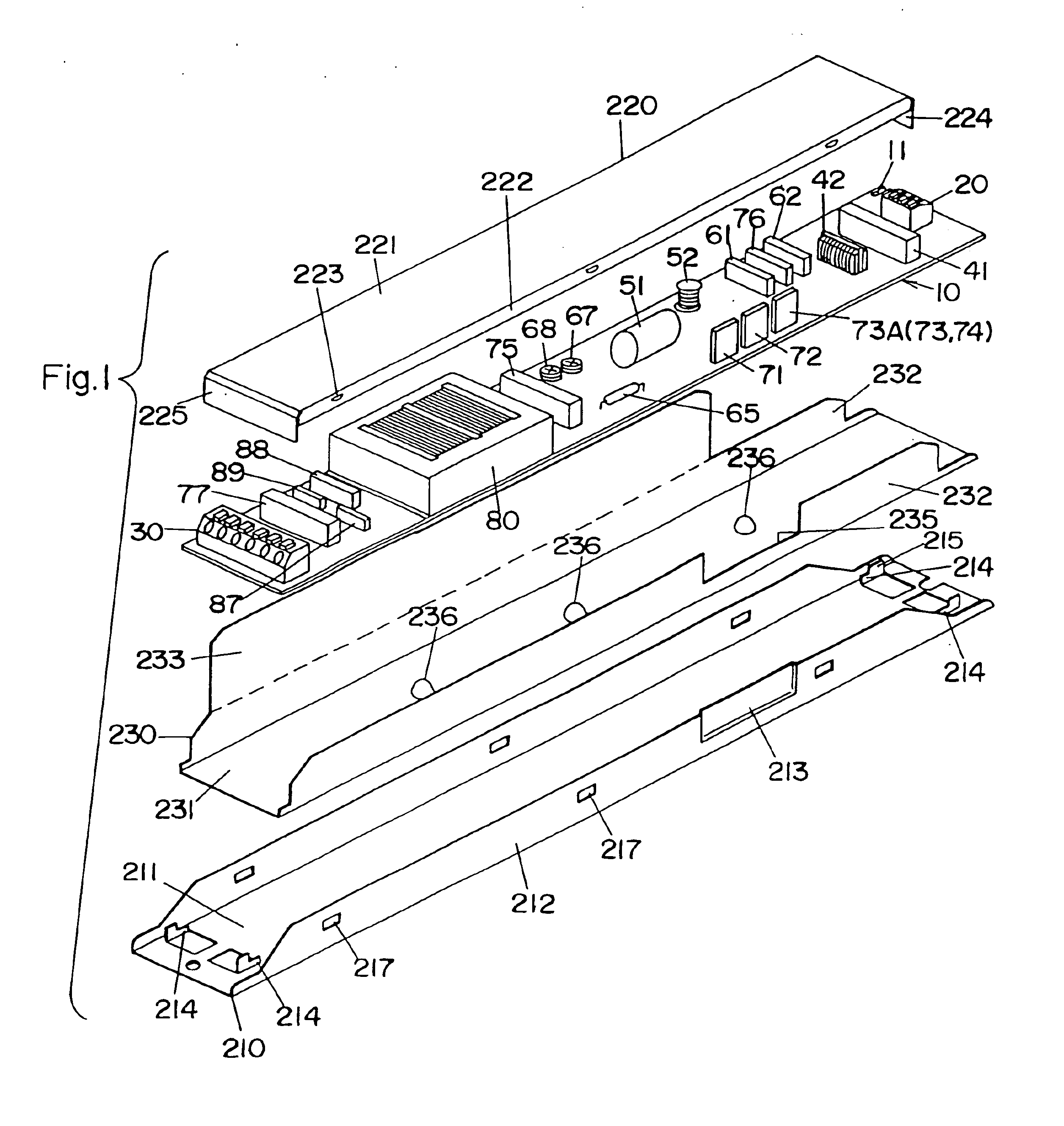
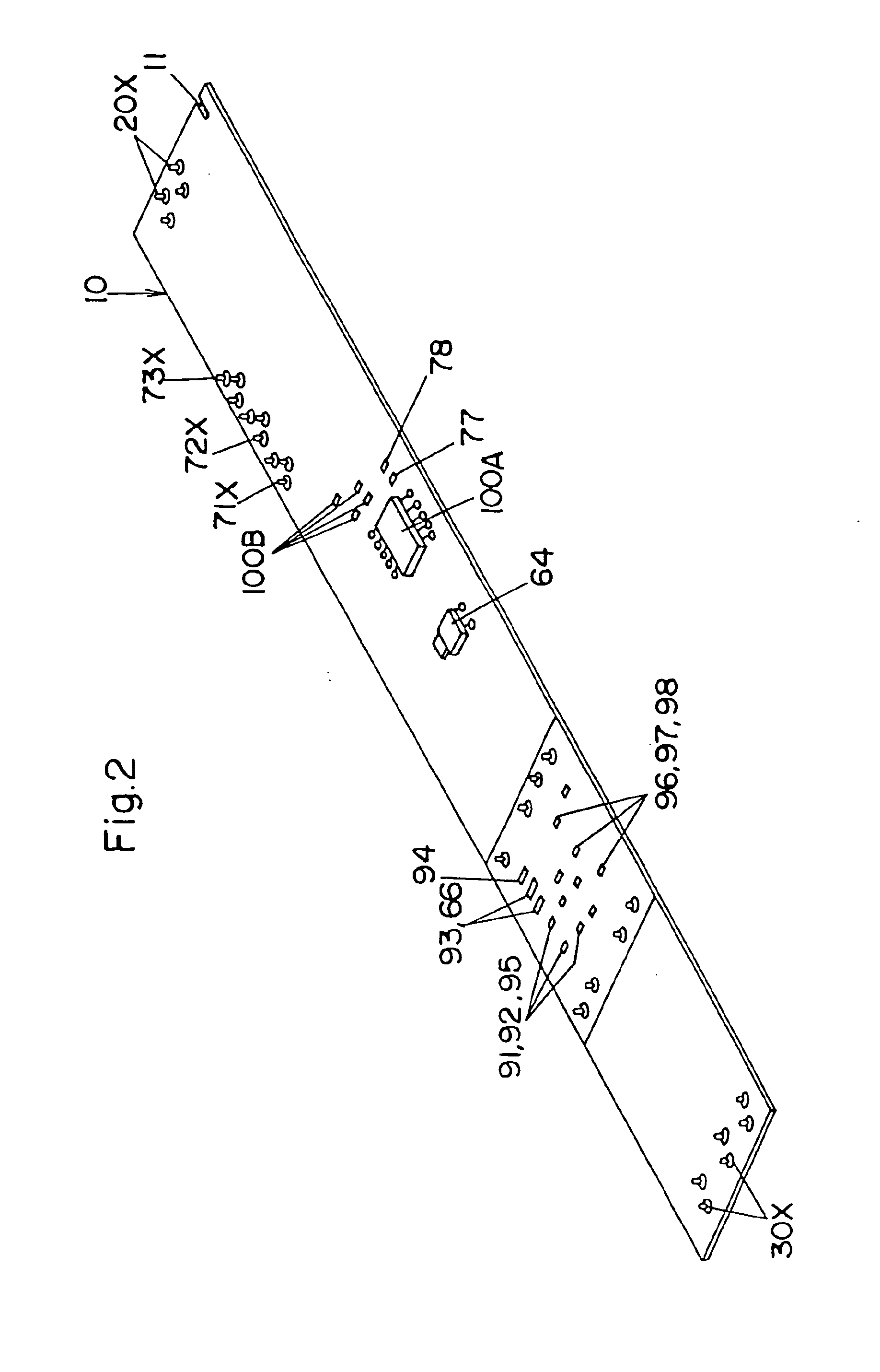
[0048]Referring now to FIG. 1, there is shown an electronic ballast in accordance with a preferred embodiment of the present invention. The ballast comprises a circuit board 10 mounting various electric parts forming an electric circuit of the ballast, a tubular casing composed of a lower case 210 and an upper case 220 to enclose the circuit board, and a dielectric sheet 230 covering the circuit board 10 as well as the electric parts for insulating the same from the casing. The casing is made of a metal such as steel and aluminum. The circuit board 10 is of an elongated configuration and provided on its top surface at its opposite longitudinal ends respectively with an input terminal socket 20 for wiring connection with an AC mains 21 and with an output terminal socket 30 for wiring connection with discharge lamps LA1 and LA2. The circuit board is made of a phenol resin impregnated paper or a composite epoxy material (CEM).

[0049]FIG. 3 shows the ballast circuit which is designed to ...


PUM


Abstract

An electronic ballast for a discharge lamp has a compact arrangement of electric parts. The ballast includes an AC-DC converter and an inverter giving a high frequency output voltage for operating the lamp. The inverter includes switching elements, a control circuit, and an output transformer for connection with the lamp. A single circuit board mounts the electric parts forming the converter and the inverter. The circuit board is accommodated within a tubular casing together with a dielectric sheet which is provided for insulating the circuit board as well as the electric parts from the casing. The output transformer is mounted on a top surface of the circuit board together with some of the other electric parts. The ballast includes chip components forming a detection circuit for lamp condition, and the circuit board mounts the chip components on a bottom surface at a location immediately opposite of the output transformer.

Description

TECHNICAL FIELD[0001]The present invention relates to an electronic ballast for a discharge lamp, and more particularly to an assembly of the electronic ballast which is added with a sophisticated function but is made compact enough to be installed in a limited space.BACKGROUND ART[0002]A prior art electronic ballast for a discharge lamp has been designed to assemble various electric parts forming the circuits of the ballast into a single casing. In the prior ballast, it has been a practice to use a circuit board which mounts on its one surface the electric parts and is assembled into the casing. When the ballast is required to have an added function of, for example, controlling the operation of the discharge lamp based upon the operating condition of the discharge lamp, the circuit board is designed to mount a corresponding number of parts forming a detection circuit of detecting the operating condition of the discharge lamp, and therefore requires an extra space for accommodating ...

Claims


Application Information

Patent Timeline
Patent Type & Authority Patents(United States)
IPC IPC(8): H05B41/02H05B41/282H05B41/298H05B41/28H05K1/18H05B41/00H05K3/34F21V23/00H05B41/24
CPCH05B41/02H05B41/28H05B41/2827H05B41/2981H05B41/2985H05K1/18H05K1/181H05K3/3415H05K3/3447H05K2201/10015H05K2201/10022H05K2201/1003H05K2201/10545H05K2201/10636Y02P70/50
Inventor YAMANAKA, YUKIOMIKI, NOBUKAZUKONO, TADAHIRONISHIDA, TOSHIHIROKADO, YOSHIKAZU
Owner MATSUSHITA ELECTRIC WORKS LTD
Why Eureka
Try Eureka