System for storing and dispensing paper clips

a paper clip and system technology, applied in the field of office supplies and equipment, can solve the problems of labor-intensive pre-loading of paper clips, system purchase and operation costs, and the limitations or drawbacks of each type of conventional dispenser, and achieve the effects of convenient and economical manner, convenient and economical use, and flexible form and function

Inactive Publication Date: 2007-11-27
EDENS MICHELLE O
View PDF28 Cites 3 Cited by
  • Summary
  • Abstract
  • Description
  • Claims
  • Application Information

AI Technical Summary

Benefits of technology

[0008]The present invention provides a versatile system for storing and dispensing paper clips in an easy and economical manner. The system of the present invention provides one at a time paper clip dispensing from a manual system. The present invention requires minimal effort to load and dispense paper clips. A user pours or places a supply of paper clips into a storage compartment (e.g., hopper, bin)—one that is able to store a relatively large number of paper clips. When a paper clip is needed, the user activates an actuating mechanism (e.g., a push button, a lever) and a single paper clip is retrieved from the storage compartment and delivered to a receptacle. The user retrieves the single paper clip from the receptacle quickly and easily, and the system is immediately ready to dispense another paper clip. The systems and components throughout the present invention are versatile in their form and function. The present invention may thus be economically produced in a wide variety of aesthetic styles and forms, catering to a wide range of consumer demands. The present invention thus provides manual, one at a time paper clip dispensing in an easy, efficient and cost-effective manner.
[0009]The system of the present invention provides a housing within or about which a number of subsystems or components are disposed. This housing may be configured, shaped or otherwise formed to address aesthetic desires. The present invention provides a storage component that collects and holds paper clips for dispensing. The present invention provides a sorting component, which manipulates paper clips in order to facilitate one at a time dispensing. The present invention provides a gate component, which facilitates removal of a single paper clip from the storage component. A retrieval system, upon stimulus from a user-initiated actuating system, conducts a single paper clip from the gate component to a retrieval receptacle. The user retrieves the paper clip from the receptacle, and the system is ready to dispense another paper clip.

Problems solved by technology

Each such type of conventional dispenser also has certain limitations or drawbacks.
Unfortunately, such systems usually cost more to purchase and operate than comparable manual systems.
Such systems typically require electric power, and must thus consume power from either a battery or power outlet source.
Furthermore, such systems may require the purchase and use of special, pre-loaded paper clip supplies in order to operate properly.
Alternatively, such systems may require labor-intensive pre-loading of paper clips into specialized clips or hoppers essential to automated dispensing.
In many cases, only a limited, relatively small number of paper clips may be loaded at one time—resulting in more frequent refills.
In contrast, conventional manual dispensers are often simple and cheap.
Most often, however, conventional manual dispensers do not provide one at a time dispensing.
Again, such dispensing usually does not provide one at a time dispensing, as the user is left to pick through whatever number of clips that the magnetic means happened to retrieve.
In some cases, a user may have to exert a certain amount of effort to separate a paper clip from the magnetic means.
Unfortunately, however, such conventional dispensers generally require some amount of laborious pre-loading, such as loading paper clips into a spring-loaded cartridge.
Furthermore, such conventional dispensers only hold a relatively small number of paper clips per loading, requiring frequent reloading by a user.

Method used


Image

  • System for storing and dispensing paper clips
  • System for storing and dispensing paper clips
  • System for storing and dispensing paper clips

Examples


Embodiment Construction

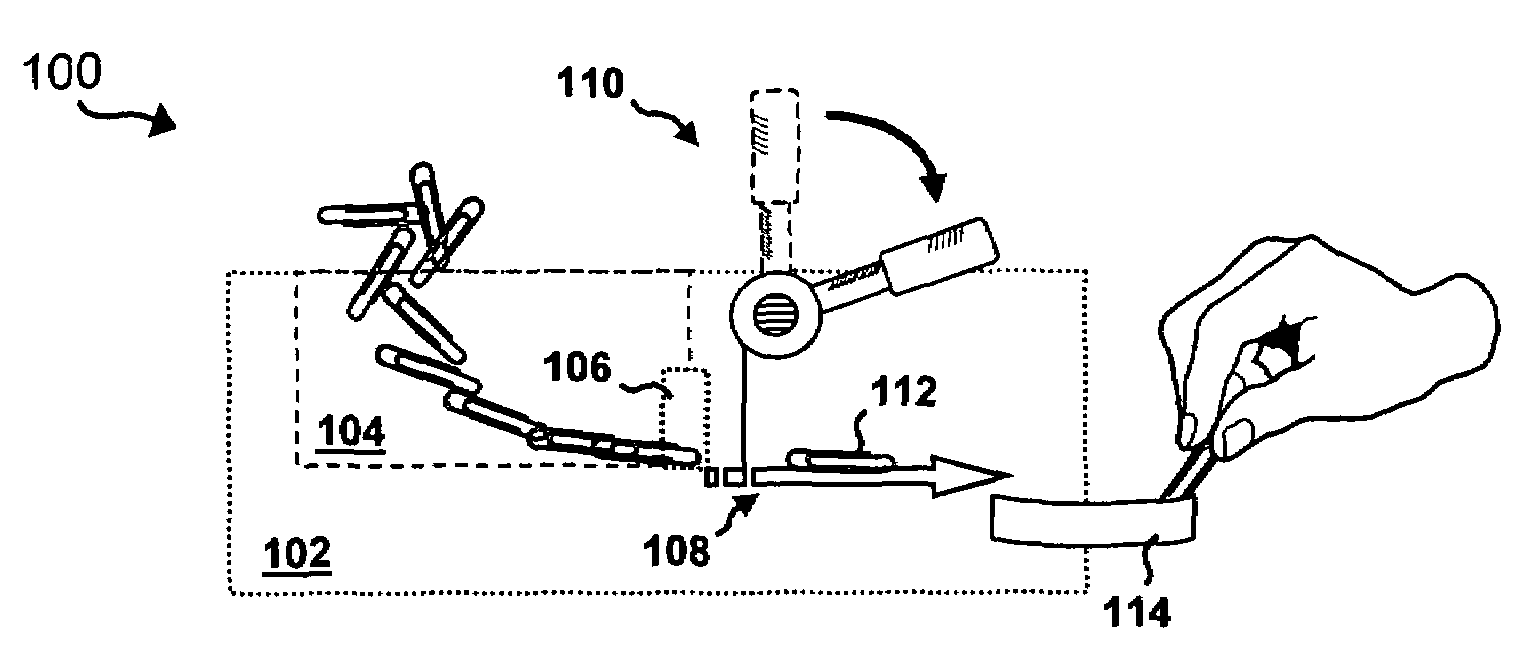
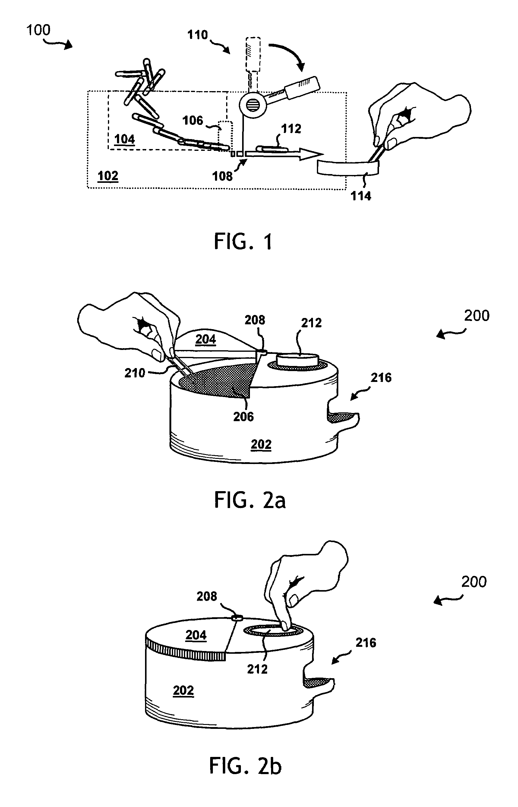
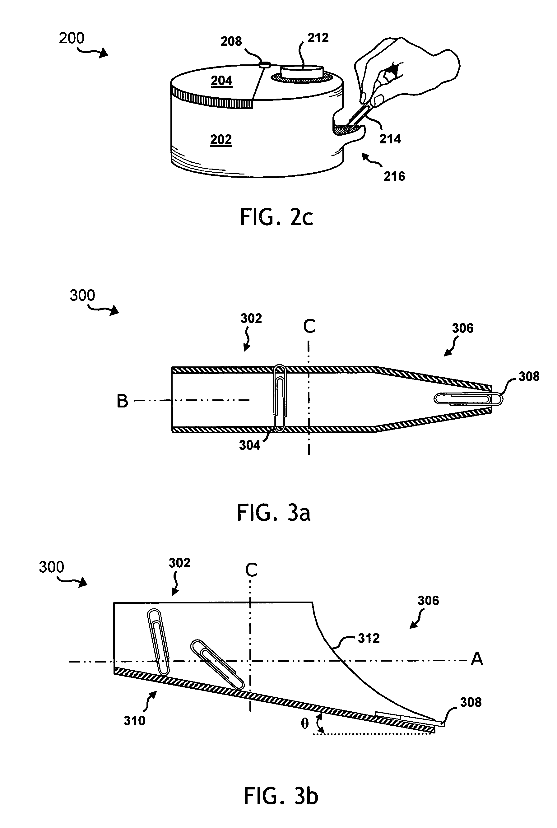
[0026]While the making and using of various embodiments of the present invention are discussed in detail below, it should be appreciated that the present invention provides many applicable inventive concepts, which can be embodied in a wide variety of specific contexts. The invention will now be described and illustrated in conjunction with a system for storing and dispensing metallic, wire-type paper clips. The specific embodiments discussed herein are, however, merely illustrative of specific ways to make and use the invention and do not limit the scope of the invention.

[0027]A system according to the present invention stores and dispenses paper clips in an easy, economical and versatile manner. A system according to the present invention provides one at a time paper clip dispensing from a manually operated system. The present invention requires only minimal effort to load and dispense paper clips. A user pours or otherwise deposits a supply of paper clips into a storage compartme...


PUM


Abstract

The present invention defines a system (100) for one-at-a-time paper clip dispensing. The system includes a housing (102), and a retrieval receptacle (114) disposed somewhere along the exterior of the housing. A storage component (104) is disposed along or within the housing, and is adapted to receive loose paper clips. A gate component (106) is operably coupled to the storage component, and a sorting component is incorporated within the storage or gate component(s). An actuating system (110) is disposed somewhere within or along the housing. A retrieval system (112) is disposed between the receptacle and the storage component. The retrieval system is adapted to retrieve a single paper clip from the gate component, and deliver the paper clip to the receptacle, responsive to activation of the actuating system.

Description

TECHNICAL FIELD OF THE INVENTION[0001]The present invention relates generally to the field of office supplies and equipment and, more particularly, to apparatus and methods for storing and dispensing paper clips.BACKGROUND OF THE INVENTION[0002]Conventional paper clip dispensers are ubiquitous. A number of both automated and manual paper clip dispensers are widely available to consumers. Each such type of conventional dispenser purports to have certain advantages over the others. Each such type of conventional dispenser also has certain limitations or drawbacks.[0003]Automated conventional dispensers typically offer very fast dispensing of paper clips, often one at a time. Such dispensers generally relieve a user from having to manually pick through or untangle a cluster of paper clips in order to retrieve a single clip. Unfortunately, such systems usually cost more to purchase and operate than comparable manual systems. Such systems typically require electric power, and must thus c...

Claims


Application Information

Patent Timeline
Patent Type & Authority Patents(United States)
IPC IPC(8): B23Q7/04B65G59/04B65H3/16G07F11/10
CPCB43M99/009
Inventor EDENS, MICHELLE O.BURNS, RONALD W.
Owner EDENS MICHELLE O
Why Eureka
Try Eureka