
Multi-band planar inverted-F antennas including floating parasitic elements and wireless terminals incorporating the same

a technology of antennas and antenna components, applied in the field of communication, can solve problems such as reducing the available area for placement of other components within the housing of wireless terminals

Inactive Publication Date: 2005-09-13
SONY ERICSSON MOBILE COMM AB
View PDF26 Cites 69 Cited by
  • Summary
  • Abstract
  • Description
  • Claims
  • Application Information

AI Technical Summary

Benefits of technology

"The invention provides multi-band planar inverted-F antennas that include a floating parasitic element. These antennas can resonate in response to different electromagnetic radiation in different frequency bands. The floating parasitic element can be located between the second planar inverted-F antenna branch and the ground plane, or it can be above or below the second branch. The multi-band antenna can also include a dielectric substrate with the first and second planar inverted-F antenna branches mounted thereon, and an RF feed and ground contact coupled to the branches. The technical effect of the invention is to provide a multi-band antenna that can resonate in response to a wide range of electromagnetic radiation in different frequency bands."

Problems solved by technology

This may decrease the available area for placement of other components within the housing of the wireless terminal.

Method used


Image

  • Multi-band planar inverted-F antennas including floating parasitic elements and wireless terminals incorporating the same
  • Multi-band planar inverted-F antennas including floating parasitic elements and wireless terminals incorporating the same
  • Multi-band planar inverted-F antennas including floating parasitic elements and wireless terminals incorporating the same

Examples


Embodiment Construction

[0018]The invention will now be described more fully hereinafter with reference to the accompanying drawings, in which embodiments of the invention are shown. This invention may, however, be embodied in many different forms and should not be construed as limited to the embodiments set forth herein; rather, these embodiments are provided so that this disclosure will be thorough and complete, and will fully convey the scope of the invention to those skilled in the art.

[0019]In the drawings, the thickness of lines, layers and regions may be exaggerated for clarity. It will be understood that when an element, such as a layer, region or substrate, is referred to as being “on” another element, it can be directly on the other element or intervening elements may also be present. In contrast, when an element is referred to as being “directly on” another element, there are no intervening elements present. It will also be understood that, when an element is referred to as being “connected” or ...


PUM


Abstract

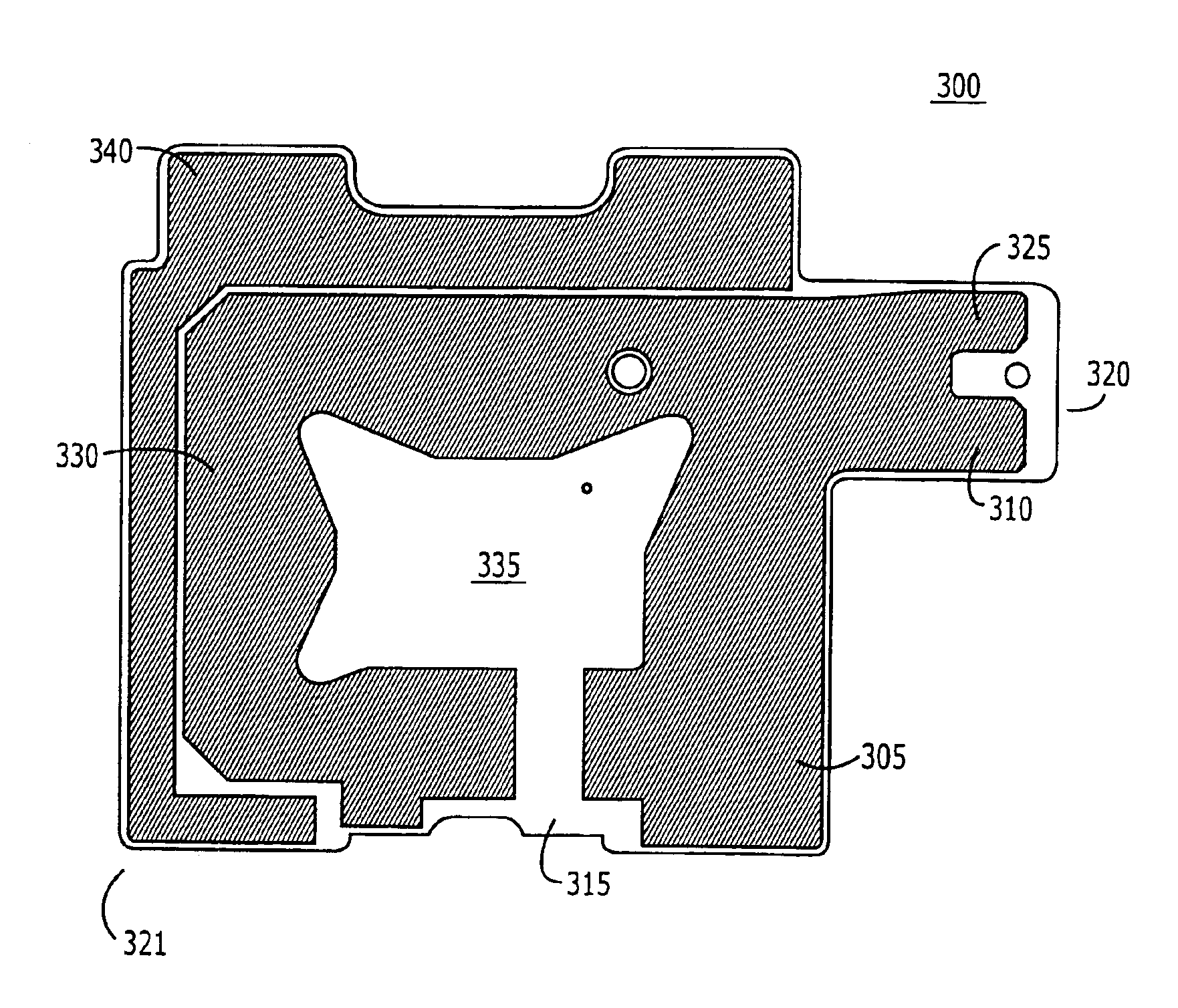
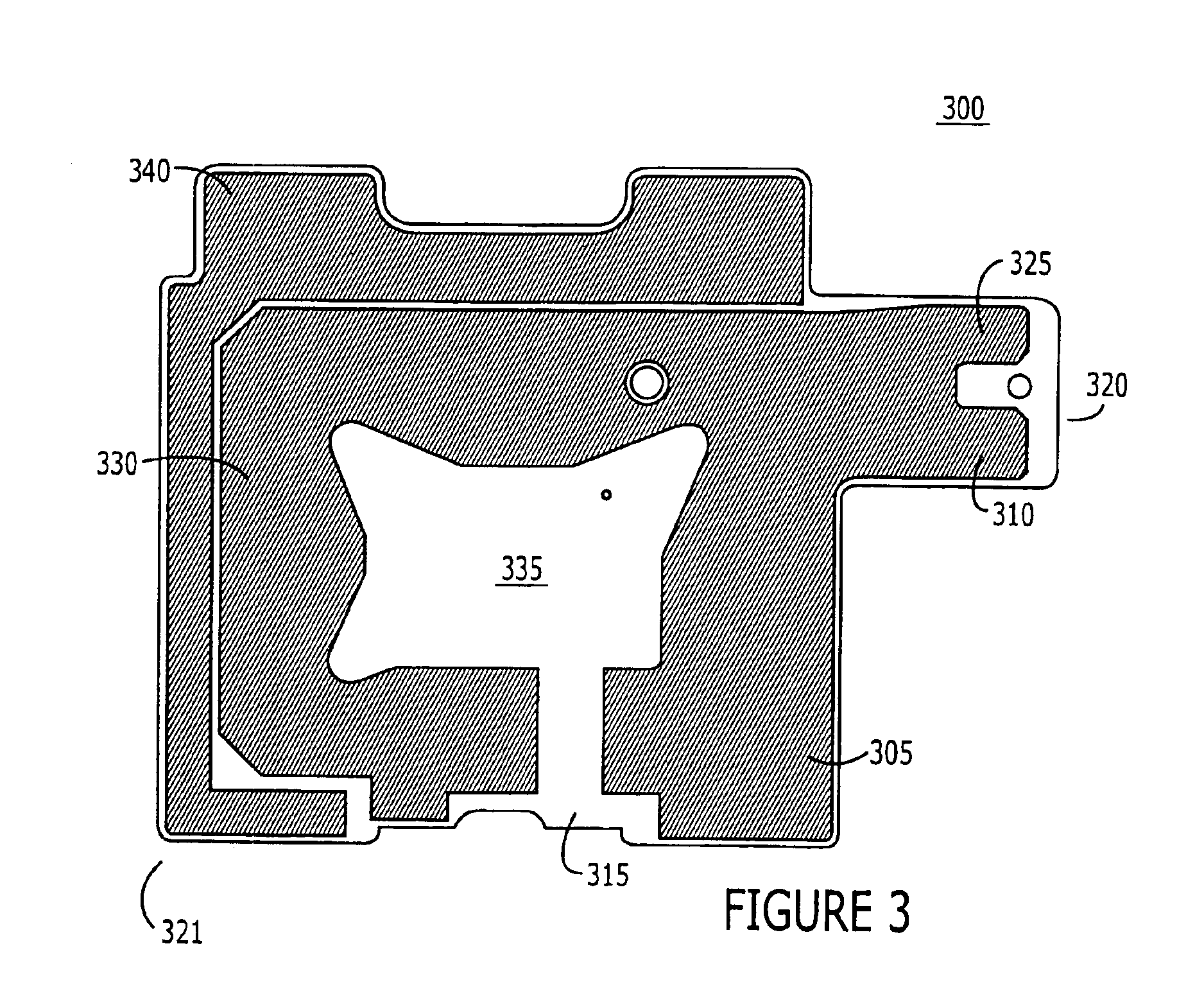
A multi-band planar inverted-F antenna includes a floating parasitic element. For example, a planar inverted-F antenna includes first and second planar inverted-F antenna branches that extend on a dielectric substrate. The first planar inverted-F antenna branch is configured to resonate in response to first electromagnetic radiation in a first frequency band. The second planar inverted-F antenna branch is configured to resonate in response to second electromagnetic radiation in a second frequency band. The floating parasitic element is configured to electromagnetically couple to the second planar inverted-F antenna branch when, for example, the second planar inverted-F antenna branch is excited by the electromagnetic radiation provided via an RF feed (when the antenna is used to transmit). The floating parasitic element is also configured to electromagnetically couple to the second planar inverted-F antenna branch when the floating parasitic element is excited by electromagnetic radiation provided via free-space.

Description

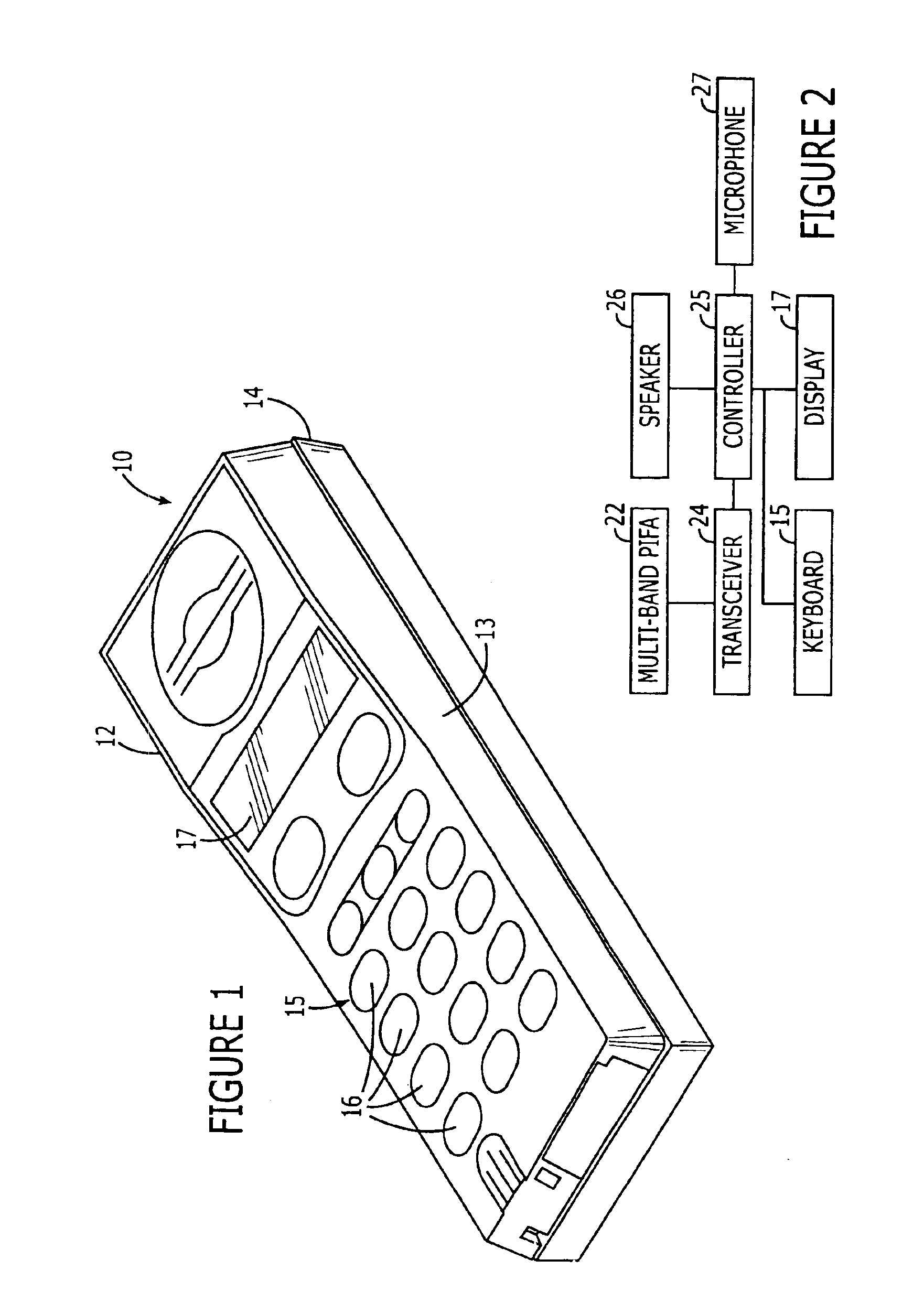
FIELD OF THE INVENTION[0001]The invention generally relates to the field of communications, and more particularly, to antennas and wireless terminals incorporating the same.BACKGROUND OF THE INVENTION[0002]Many contemporary wireless terminals, such as cell phones, are less than 11 centimeters in length. Thus, there is an interest in antennas that can be mounted inside these types of wireless terminals. A planar antenna, such as an planar inverted-F antenna, is one type of antenna that may be well suited for use within the confines of small wireless terminals. Typically, conventional inverted-F antennas include a conductive element that is spaced apart from a ground plane. Exemplary inverted-F antennas are described, for example, in U.S. Pat. Nos. 6,639,560 and 6,573,869, the disclosures of which are incorporated herein by reference in their entireties.[0003]Wireless terminals may operate in multiple frequency bands in order to provide operations in multiple communications systems. F...

Claims


Application Information

Patent Timeline
Patent Type & Authority Patents(United States)
IPC IPC(8): H01Q5/00H01Q9/04H01Q1/24H01Q5/10H01Q5/371H01Q5/378
CPCH01Q1/243H01Q5/378H01Q5/371H01Q9/0421
Inventor VANCE, SCOTT L.
Owner SONY ERICSSON MOBILE COMM AB
Learn More