Recoiling striking device

a striking device and coil technology, applied in the field of striking devices, can solve the problems of preventing further work and serious health problems

Inactive Publication Date: 2005-09-20
SEES JERRY
View PDF12 Cites 17 Cited by
  • Summary
  • Abstract
  • Description
  • Claims
  • Application Information

AI Technical Summary

Problems solved by technology

These rebound forces can eventually cause serious health

Method used


Image

  • Recoiling striking device
  • Recoiling striking device
  • Recoiling striking device

Examples


Embodiment Construction

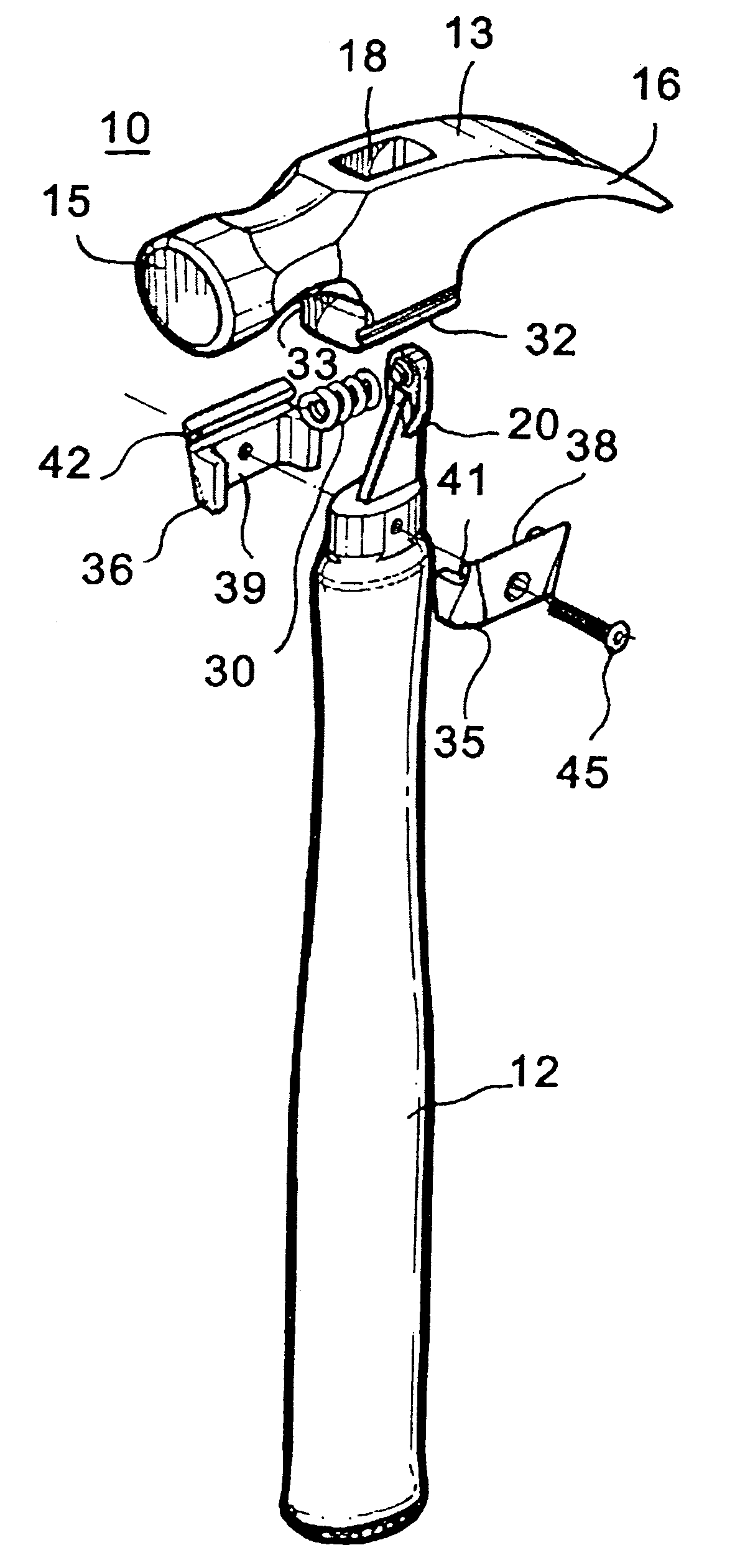
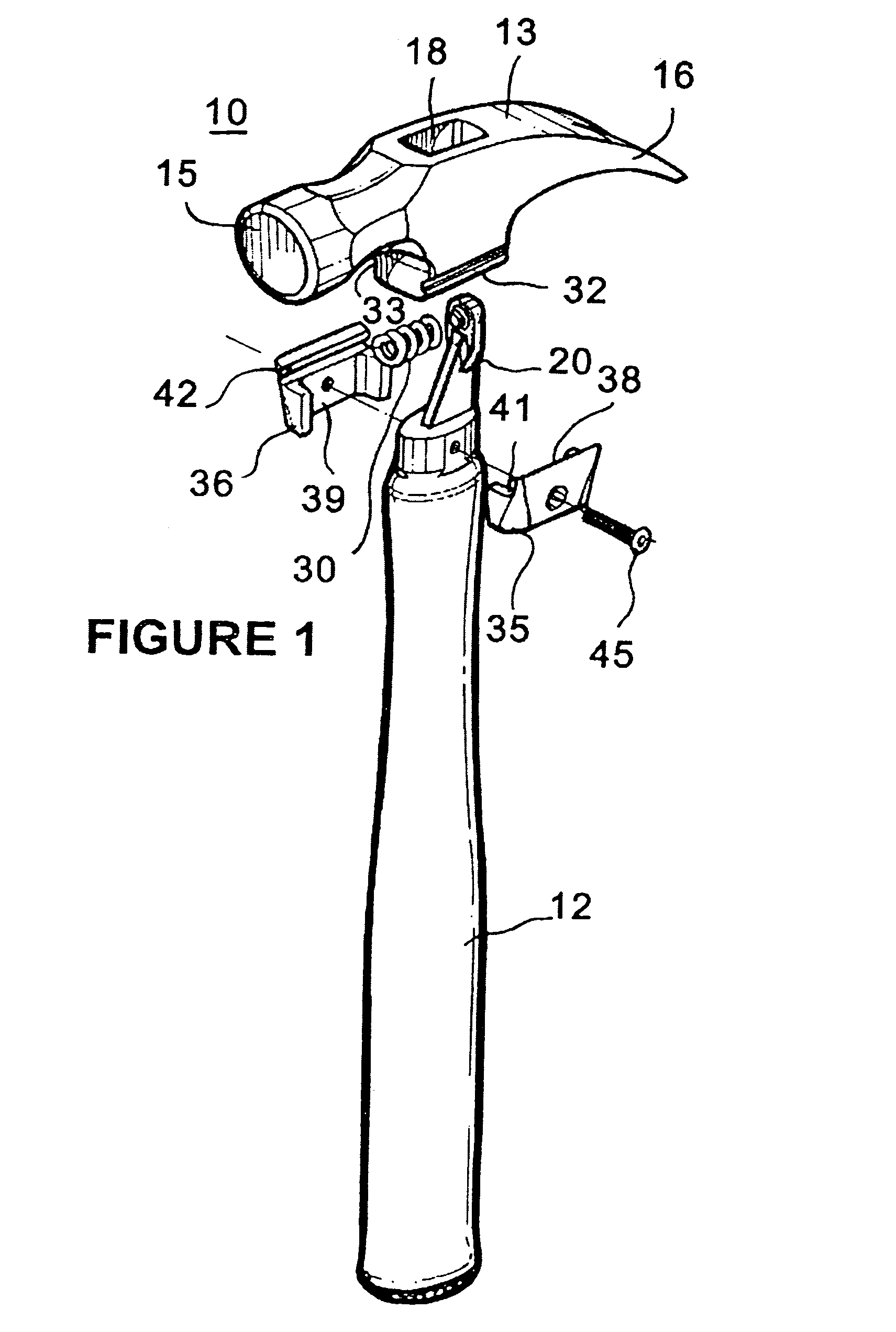
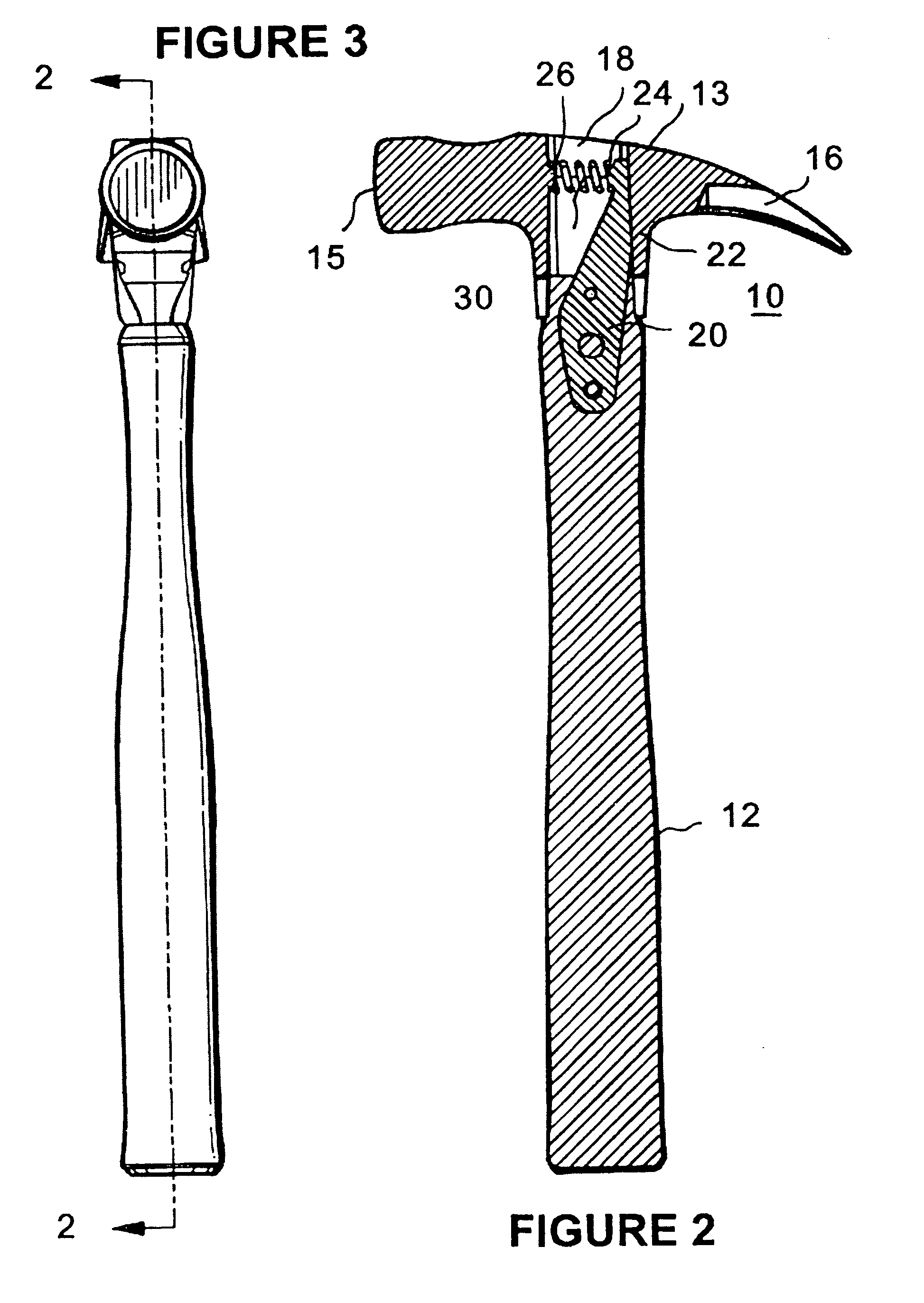
[0020]Turning now to the drawings in which like reference characters indicate corresponding elements throughout the several views, attention is directed to FIGS. 1–3, which illustrate a striking device, hereinafter hammer 10. Hammer 10 includes a handle 12 and a head 13 with a striking surface 15 and claws 16. An opening 18 is formed in head 13 for mounting head 13 on handle 12. Generally, opening 18 is similar to mounting openings formed in the heads of prior art hammers for receiving the head end of an associated handle and is defined by an inner surface having a forward surface, toward the striking surface, and a rearward surface. As in any standard hammer, head 13 is used for driving nails or striking objects and claws 16 are used for pulling nails or otherwise applying a lever action to objects. It will be understood that while claws 16 are shown in this embodiment, they may be omitted as desired.

[0021]In hammer 10, a tang 20 is imbedded in the head-end of handle 12 so as to ex...


PUM


Abstract

A striking device including a head having a striking surface and a base mounted on an end of a handle for reciprocation in a linear motion. A rail structure is carried by the end of the handle. A rail receiving structure is carried by the base and receives the rail structure for reciprocating linear motion of the head between a forward position and a rearward position. A biasing structure biases the head into the forward position.

Description

CROSS-REFERENCE TO RELATED APPLICATION[0001]This application claims the benefit of U.S. Provisional Patent Application No. 60 / 398,251, filed 24 Jul. 2002.FIELD OF THE INVENTION[0002]This invention relates to striking devices, such as hammers and the like.[0003]More particularly, the present invention relates to striking devices incorporating recoil apparatus.BACKGROUND OF THE INVENTION[0004]In the building industry, striking devices, such as hammers and the like (hereinafter “hammer”) are used for a multitude of purposes including driving nails, straightening and / or adjusting items, and various other actions requiring a striking motion from a heavy solid tool. In a days work, for example, a carpenter can perform thousands of strikes with a hammer. Each time the hammer is used to strike an object the force of the strike rebounds or reacts through the handle and against the user's hand and arm. Thus, the carpenter who performs thousands of strikes with a hammer receives thousands of s...

Claims


Application Information

Patent Timeline
IPC IPC(8): B25D1/12B25D1/00B25D1/04B25G1/01
CPCB25D1/045B25D1/12B25G1/01B25D2250/371
Inventor KREITZER, DAVID F.
Owner SEES JERRY
Why Eureka
Try Eureka