Enhanced durability hammer union

a technology of hammer unions and hammers, applied in the field of unions, can solve the problems of fatigue failure, large installation and replacement time of clamp-type couplings,

Inactive Publication Date: 2005-09-20
S P M FLOW CONTROL
View PDF13 Cites 77 Cited by
  • Summary
  • Abstract
  • Description
  • Claims
  • Application Information

AI Technical Summary

Problems solved by technology

Clamp-type couplings, however, take considerable time to install and replace, and are therefore only appropriate in relatively permanent installations.
There are some applications, however, where the cyclic nature of the loading is so severe that fatigue failure is possible.

Method used


Image

  • Enhanced durability hammer union
  • Enhanced durability hammer union
  • Enhanced durability hammer union

Examples


Embodiment Construction

[0016]Although the following detailed description contains many specific details for purposes of illustration, anyone of ordinary skill in the art will appreciate that many variations and alterations to the following details are within the scope of the invention. Accordingly, the exemplary embodiment of the invention described below is set forth without any loss of generality to, and without imposing limitations thereon, the claimed invention.

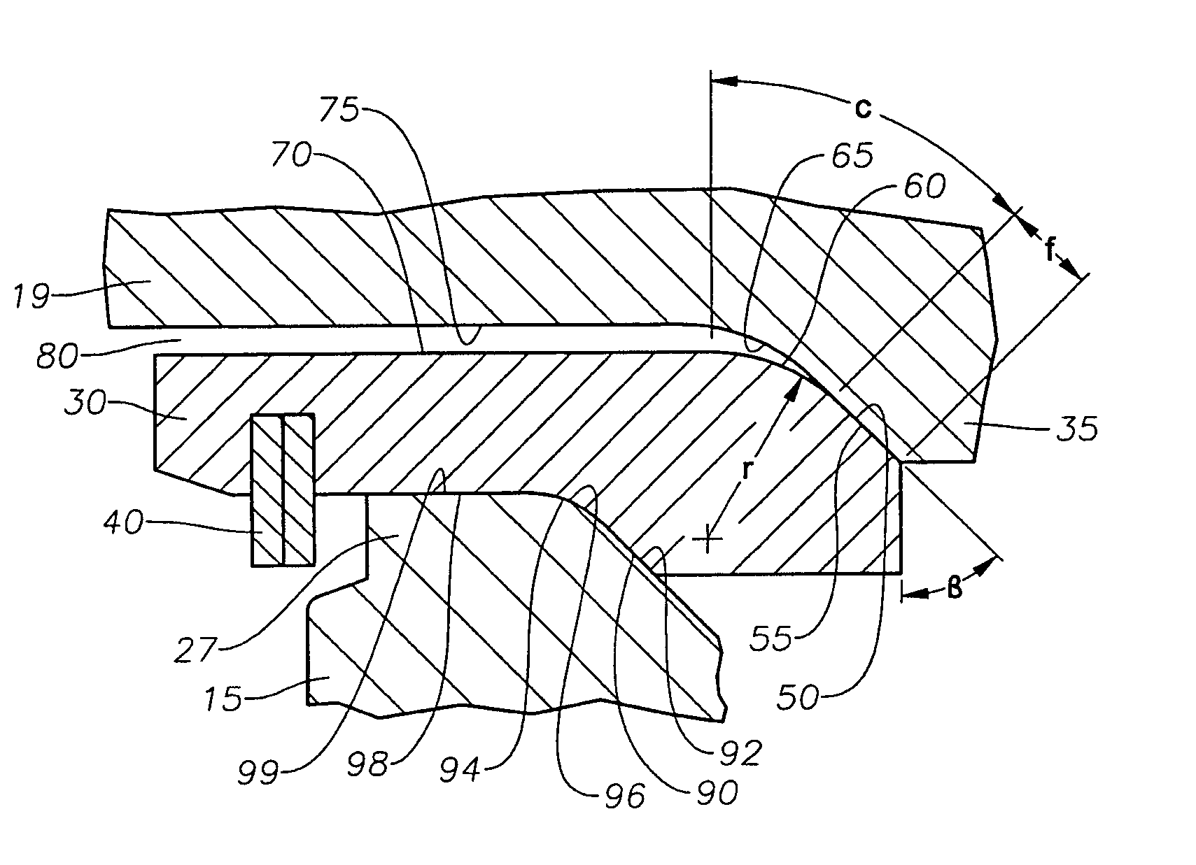
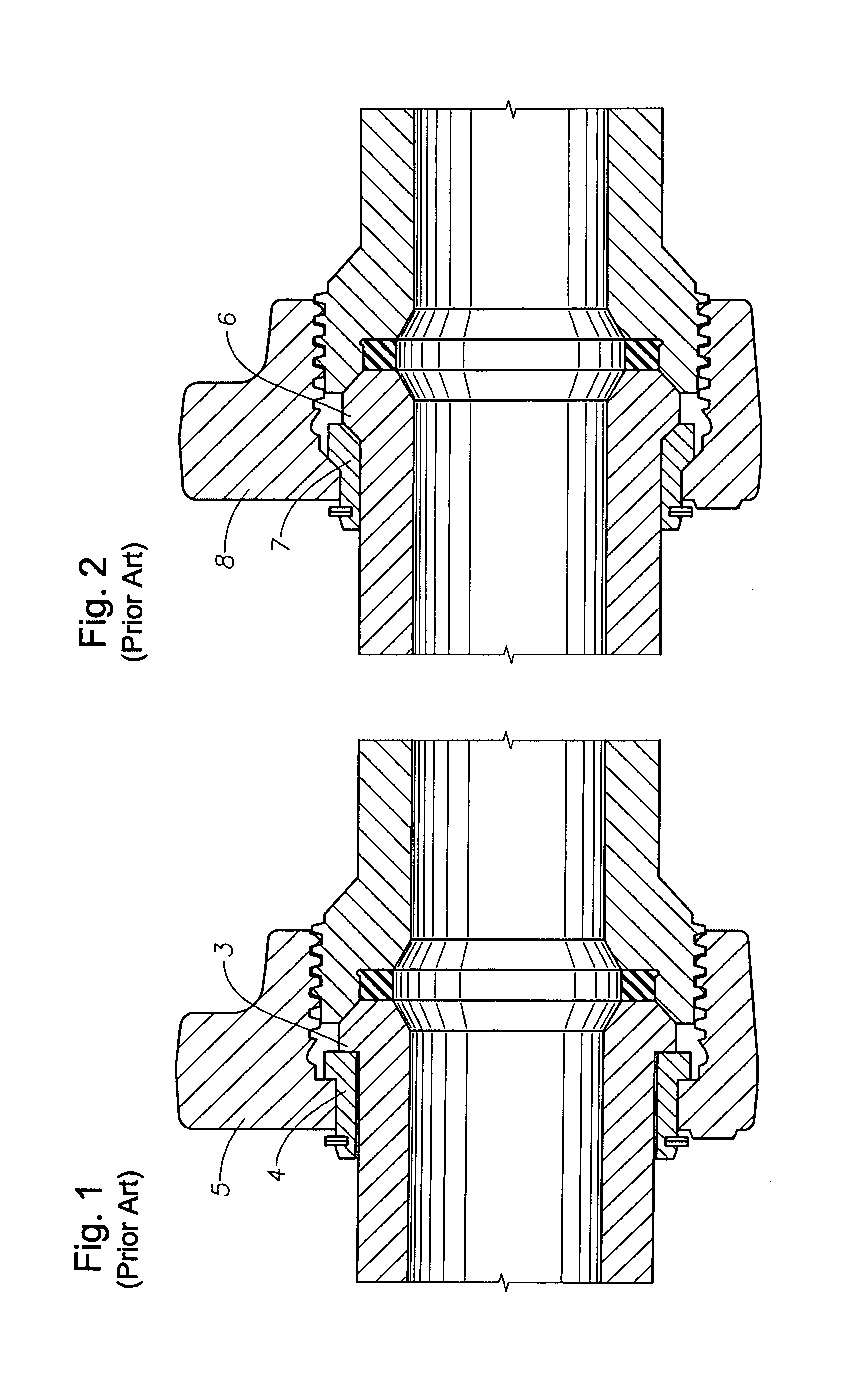
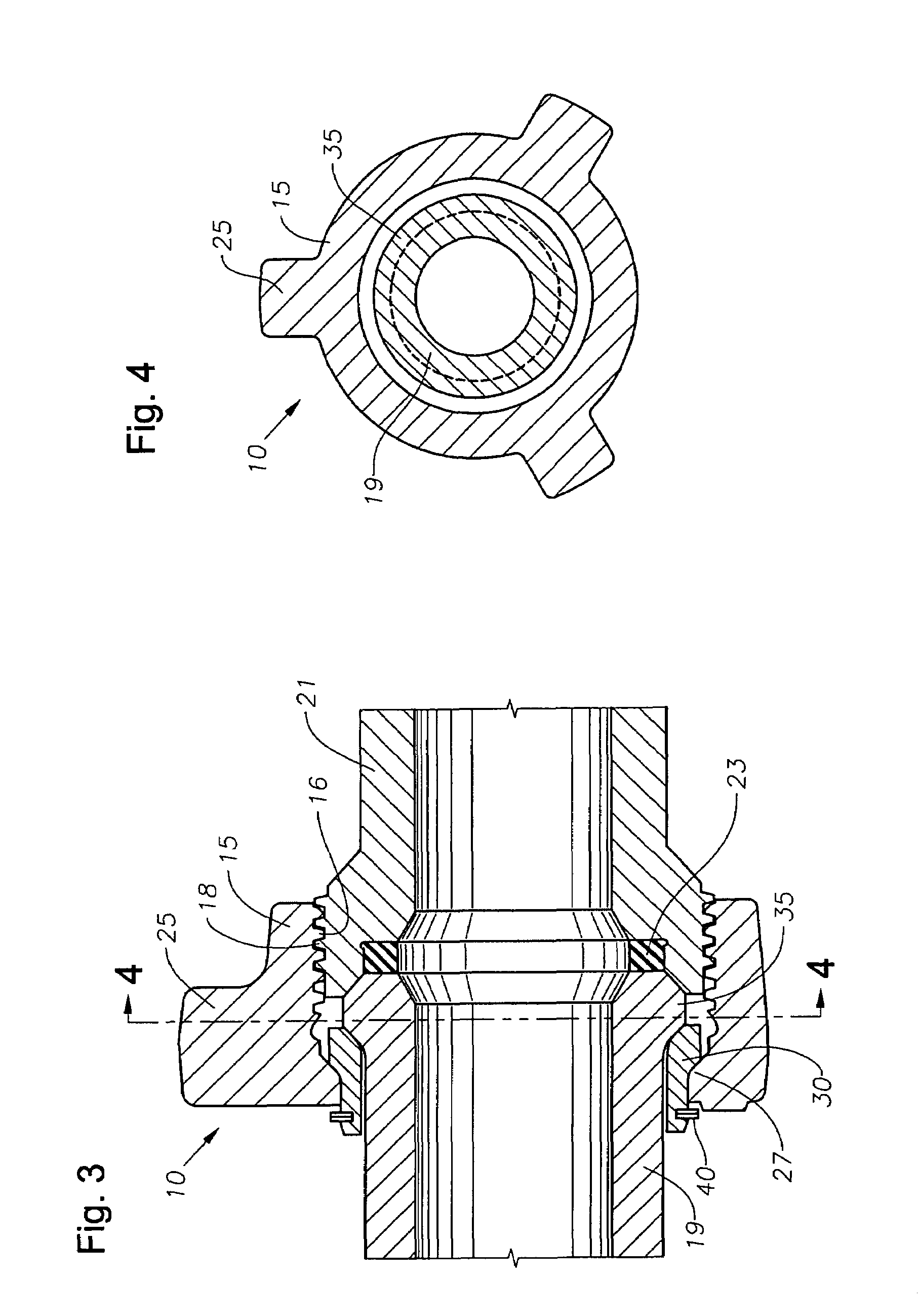
[0017]The hammer union 10 of the present invention is a flowline apparatus that joins two conduit sections 19 and 21. The conduit sections 19 and 21 are tubular in shape, and preferably include one threaded conduit section 21 and one non-threaded conduit section 19. The union 10 includes a threaded wing nut 15 for receiving and engaging the threaded conduit section 21.

[0018]As shown in FIGS. 3 and 4, the wing nut 15 surrounds and encases the end portions of the conduit sections 19 and 21 to be joined. In this manner, the wing nut 15 operates as...


PUM


Abstract

A union for connecting two tubular members. The first tubular member has an external flange, and the second tubular member has a set of external threads. An annular nut surrounds the first tubular member. The nut has an internal flange that surrounds the first tubular member, and a set of threads to engage the threads of the second tubular member. Arcuate segments are circumferentially mated between the internal flange of the nut and the external flange of the first tubular member. A flat conical surface on the inner side of the segment comes into contact with a flat conical surface on the outer side of the external flange. Curved conical surfaces tangentially align with and extend from the flat conical surfaces on the segment and the external flange. Cylindrical surfaces tangentially align and join the curved conical surfaces on the segment and the tubular member.

Description

1. FIELD OF THE INVENTION[0001]This invention relates generally to unions for connecting conduits, and relates more particularly to pressure transmitting hammer unions, which enable two coaxial sections of conduit to be connected without rotating the conduit sections.2. BACKGROUND OF THE INVENTION[0002]A pipe union for interconnecting two coaxial pipe ends is often utilized to transmit fluid under pressure during oilfield service operations. Typical high-pressure operations include mud logging, cementing, fracing, acidizing, nitrogen pumping, and other upstream well servicing applications.[0003]One such coupling apparatus for connecting two pipe ends in an oilfield flowline is a clamp-type union connection positioned at the pipe joint. A clamp surrounds the adjacent ends of the two lengths of pipe to be interconnected. The clamp is tightened around the ends of the pipe lengths by associated wing nuts and bolts, and the individual pipe sections are drawn axially toward one another, c...

Claims


Application Information

Patent Timeline
Patent Type & Authority Patents(United States)
IPC IPC(8): E21B17/02F16L35/00F16L15/08F16L19/02F16L15/00F16L19/025
CPCF16L19/025F16L19/0212
Inventor DIAZ, JUAN M.MATZNER, MARK D.
Owner S P M FLOW CONTROL
Why Eureka
Try Eureka