
Transformer

a transformer and transformer technology, applied in the field of transformers, can solve the problems of inflexible manufacturing process, inefficient mass production, and current and external interference in signal transmission, and achieve the effect of flexible and rapid manufacturing process

Inactive Publication Date: 2005-09-20
AMPHENOL TAIWAN CORP
View PDF7 Cites 20 Cited by
  • Summary
  • Abstract
  • Description
  • Claims
  • Application Information

AI Technical Summary

Benefits of technology

[0008]Accordingly, an object of the present invention is to provide a transformer, which is modularly produced and separately assembled on a communication connector for making manufacture process flexible and rapid.
[0009]Another object of the present invention is to provide a transformer which is easily assembled independent of soldering and which prevents from electromagnetic and noise interference for stable signal transmission.

Problems solved by technology

Signal transmission, especially high-speed signal transmission, is subject to current and external interference.
(1) manufacture process is inflexible.
(2) mass production is inefficient.
This makes manufacture process troublesome.

Method used


Image

  • Transformer
  • Transformer
  • Transformer

Examples


Embodiment Construction

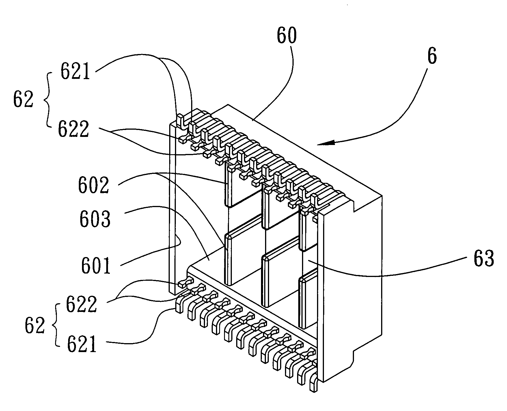
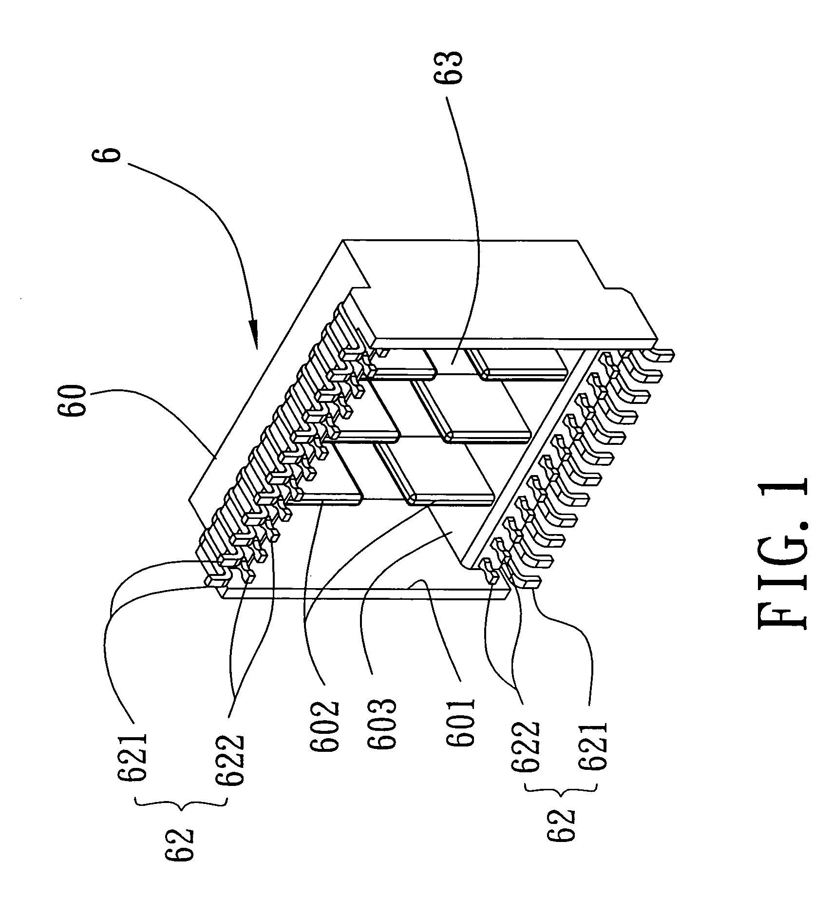
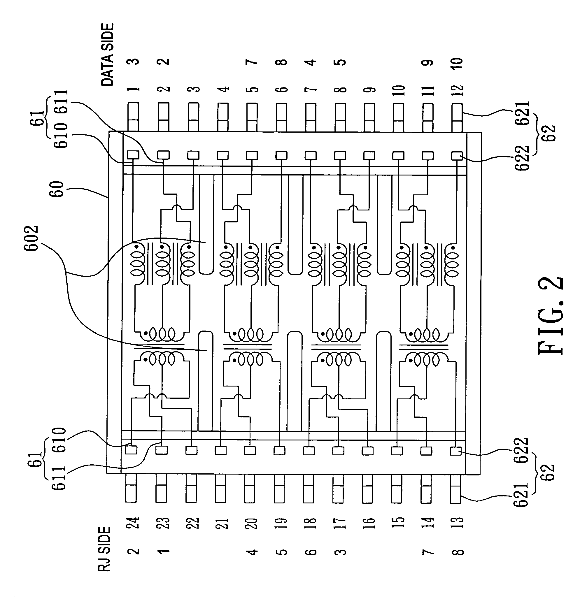
[0015]With reference to FIGS. 1 and 2, a transformer 6 in accordance with the present invention comprises a rectangular insulative housing 60, a plurality of inductive coils 61 and a plurality of soldering tails 62. The insulative housing 60 includes a bottom wall (not labeled) and four side walls (not labeled), and defines an opening 601 toward a top thereof. Two tables 603 are respectively formed at inner surfaces of two opposing sidewalls of the insulative housing 60 for positioning the soldering tails 62. A plurality of partitions 602 is formed in the insulative housing 60 and is spaced the same distance from each other for receiving the inductive coils 61. A channel 63 is defined through a middle of the partitions 602 for accommodating more inductive coils 61. Each inductive coil 61 has a first wire 610 and a second wire 611. The soldering tails 62 are mounted on two opposing sidewalls of the insulative housing 60 and extend beyond from the opening 601. Each soldering tail 62 h...


PUM


Abstract

A transformer comprises a rectangular insulative housing, a plurality of inductive coils received in the insulative housing, and a plurality of soldering tails. The insulative housing includes a bottom wall and four sidewalls, and forms a plurality of partitions therein for receiving the inductive coils. Each inductive coil has a first wire and a second wire. The soldering tails are provided at two opposing sidewalls of the insulative housing. Each soldering tail has a soldering end at exterior of the insulative housing for electrically connecting with a PCB of a communication connector, and a wiring end at interior of the insulative housing for connecting with the first wire and the second wire of the inductive coils. The transformer is modularly produced, and is tested before it is assembled to a communication connector. Thus the manufacture process is flexible and the communication connector provides stable signal transmission.

Description

BACKGROUND OF THE INVENTION[0001]1. Field of the Invention[0002]The present invention relates to a transformer, and particularly to a transformer used in a communication connector for stably transmitting signals.[0003]2. Related Art[0004]Signal transmission, especially high-speed signal transmission, is subject to current and external interference. Currently, in order to make signal transmission stable, transformers are popularly used in communication connectors for signal transmission between computers and peripherals. Such a transformer often has filtering function, as disclosed in U.S. Pat. Nos. 4,754,370, 5,015,204, 5,139,442, 5,687,233, 5,872,492, 5,833,496, 6,102,741 and 6,456,180.[0005]The conventional transformer usually has inductive / impedance coils. Each inductive / impedance coil has two ends respectively serving for mating with a mating connector and soldering to a PCB, sometimes serving for connecting with the communication connector and soldering to a PCB. There are some...

Claims


Application Information

Patent Timeline
IPC IPC(8): H01F27/02H01F19/00H01F27/04
CPCH01F19/00H01F27/02H01F27/04H01F2038/006
Inventor CHIH-MIN, LIN
Owner AMPHENOL TAIWAN CORP
Learn More