

Image signal processing apparatus and method
a signal processing apparatus and image technology, applied in the direction of signal generators with optical-mechanical scanning, color signal processing circuits, television systems, etc., can solve the problem of not being able to create a new field between each pair, and achieve the effect of smoothing the motion of an image, suppressing the flicker disturbance of the plane, and synergistic improvement of image quality
- Summary
- Abstract
- Description
- Claims
- Application Information
AI Technical Summary
Benefits of technology
Problems solved by technology
Method used
Image

Examples
first embodiment
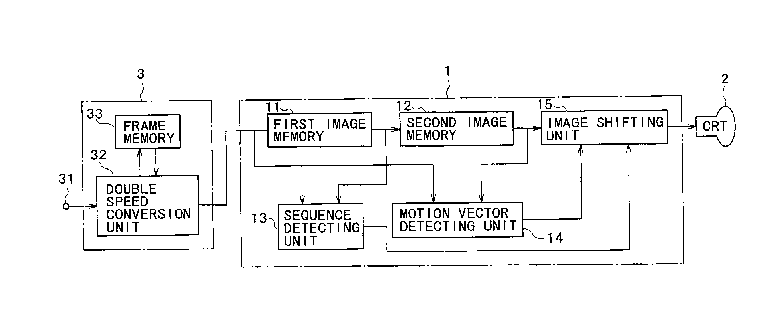
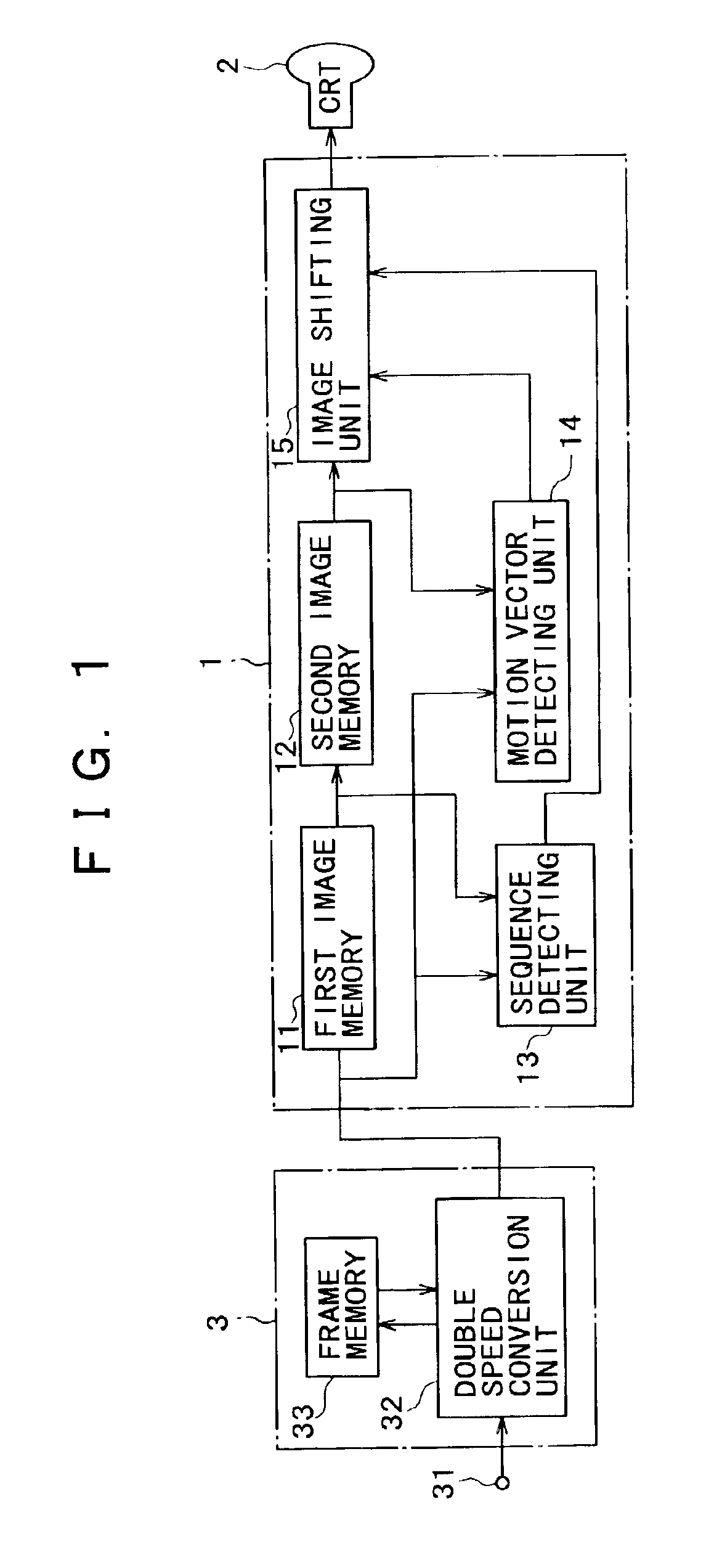
[0045]FIG. 1 is a block diagram of an image signal processing apparatus 1 in the present invention. The image signal processing apparatus 1 is for example included in a television receiver using the PAL (Phase Alternation by Line) system, and is supplied with a telecine-converted image signal. As shown in FIG. 1, the image signal processing apparatus 1 includes: a first image memory 11; a second image memory 12; a sequence detecting unit 13; a motion vector detecting unit 14; and an image shifting unit 15.
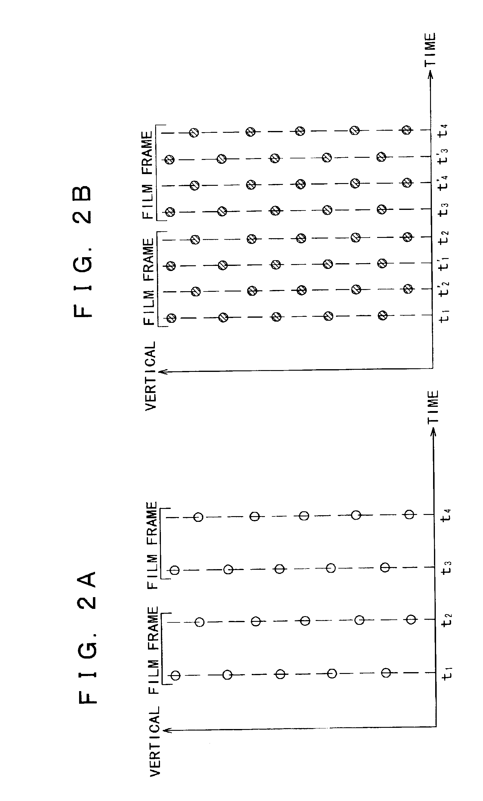
[0046]The first image memory 11 is sequentially supplied with an interlaced image signal of 100 fields per second, for example, which is generated by subjecting a telecine-converted image to double speed conversion and whose film frame is formed by four fields.
[0047]The first image memory 11 stores one frame of the image signal supplied thereto in field units. That is, an image signal outputted from the first image memory 11 is one frame after the image signal supplied to the first...
second embodiment
[0083]the present invention will next be described in detail with reference to drawings.
[0084]FIG. 10 is a block diagram of an image signal processing apparatus 7 according to the second embodiment.
[0085]The image signal processing apparatus 7 is for example included in a television receiver using the PAL (Phase Alternation by Line) system, and is supplied with a television signal (hereinafter referred to as a TV signal).
[0086]As shown in FIG. 10, the image signal processing apparatus 7 includes: a first image memory 71; a motion vector detecting unit 74; and an image shifting unit 15. For the same circuit components as in the image signal processing apparatus 1 of the first embodiment, reference is to be made to the description of the first embodiment, and description of the circuit components will be omitted.
[0087]The first image memory 71 is sequentially supplied with an interlaced image signal of 100 fields per second, for example, which is generated by subjecting a TV signal to...
third embodiment
[0104]the present invention will next be described in detail with reference to drawings.
[0105]FIG. 16 is a block diagram of an image signal processing apparatus 9 according to the third embodiment.
[0106]The image signal processing apparatus 9 is for example included in a television receiver using the PAL system, and is supplied with a telecine-converted image signal or a TV signal.
[0107]As shown in FIG. 16, the image signal processing apparatus 9 includes: a first image memory 11; a second image memory 12; a sequence detecting unit 13; a motion vector detecting unit 14; an image shifting unit 15; and a data selecting unit 91. For the same circuit components as in the image signal processing apparatus 1 of the first embodiment, reference is to be made to the description of the first embodiment, and description of the circuit components will be omitted.
[0108]The sequence detecting unit 13 is supplied with an image signal supplied to the first image memory 11 and a one-frame delayed im...
PUM
 Abstract
Description
Claims
Application Information