PCMCIA card

a technology of pcmcia and card, applied in the field of pcmcia cards, can solve the problems of metal shields that are limited in shape and aesthetically less appealing than plastics, metal panels that are less aesthetically pleasing than plastics, and manufacturing costs, and achieve the effect of preventing the separation of plastics and metal panels, and facilitating us

Inactive Publication Date: 2005-09-20
TE CONNECTIVITY CORP
View PDF7 Cites 10 Cited by
  • Summary
  • Abstract
  • Description
  • Claims
  • Application Information

AI Technical Summary

Benefits of technology

[0009]The present invention provides for a card having a configuration that facilitates the use of aesthetically-pleasing moldable materials for a portion of the cover while avoiding the problems in conventional metal-to-plastic construction as mentioned above. To this end, the plastic panel and the conductive metal panel are configured to interconnect by flowing the plastic around anchor structures of the metal panel. More specifically, the conductive panel is configured with tabs having barbs thereon and the plastic panel is configured with slots to receive the barbs. Upon application of sufficient energy, the plastic flows around the bards, thereby anchoring the tabs in the plastic and preventing the separation of the plastic and metal panels.

Problems solved by technology

Although effective as a protective shield against both physical damage and EMI, the metal shield tends to be limited in shape and is aesthetically less appealing than plastic.
As the number of press runs increases, however, so does manufacturing costs.
Additionally, metal panels tend to be less aesthetically pleasing than plastic due to limitations in the texture and finish of the panel body.
Specifically, plastic panels tend to be difficult to join to complementing metal panels using traditional techniques such as adhesion.
Although effective, this approach requires additional components and relatively complex metal panels and manufacturing steps, and therefore tends to be relatively expensive.

Method used


Image

  • PCMCIA card
  • PCMCIA card
  • PCMCIA card

Examples


Embodiment Construction

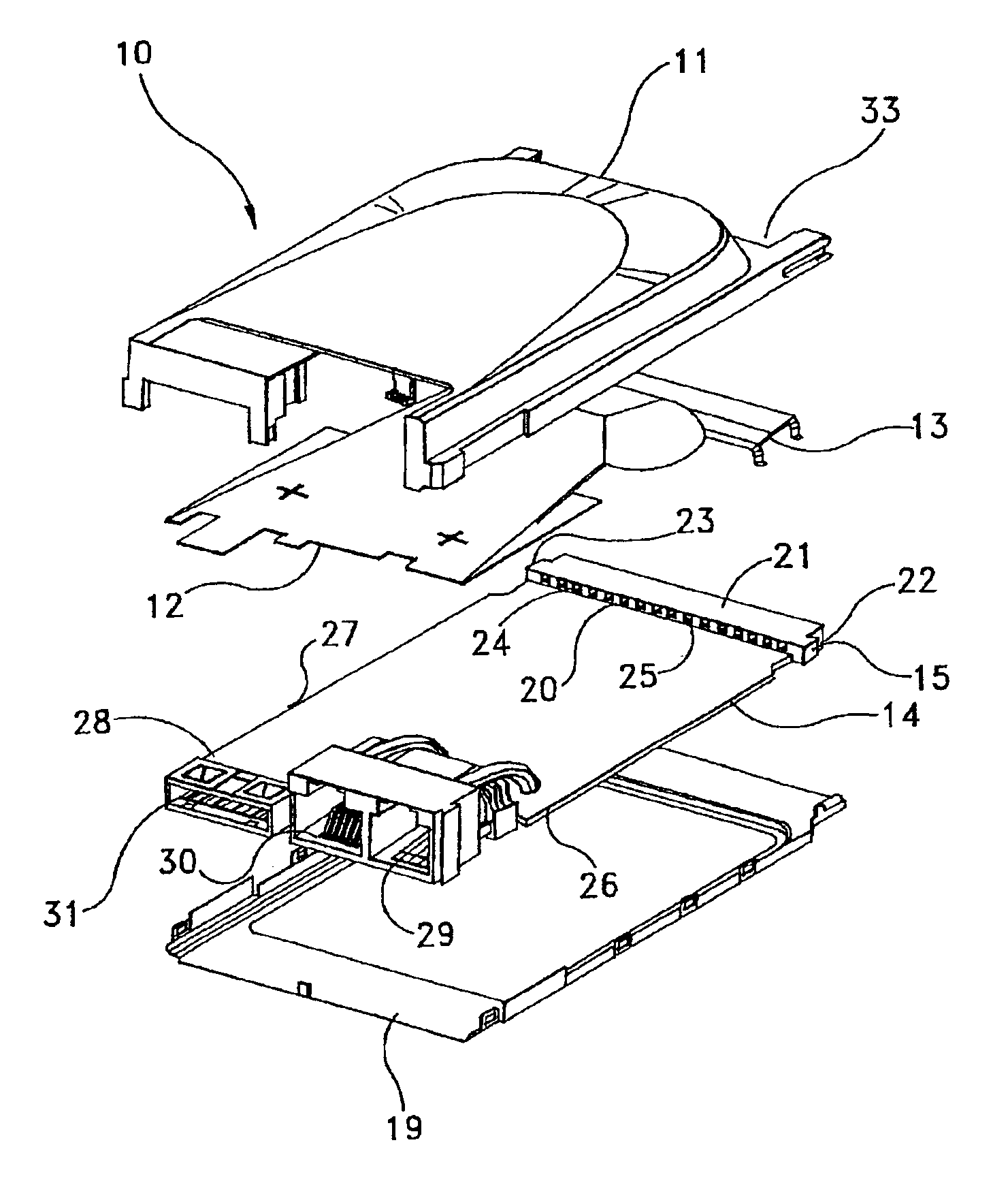
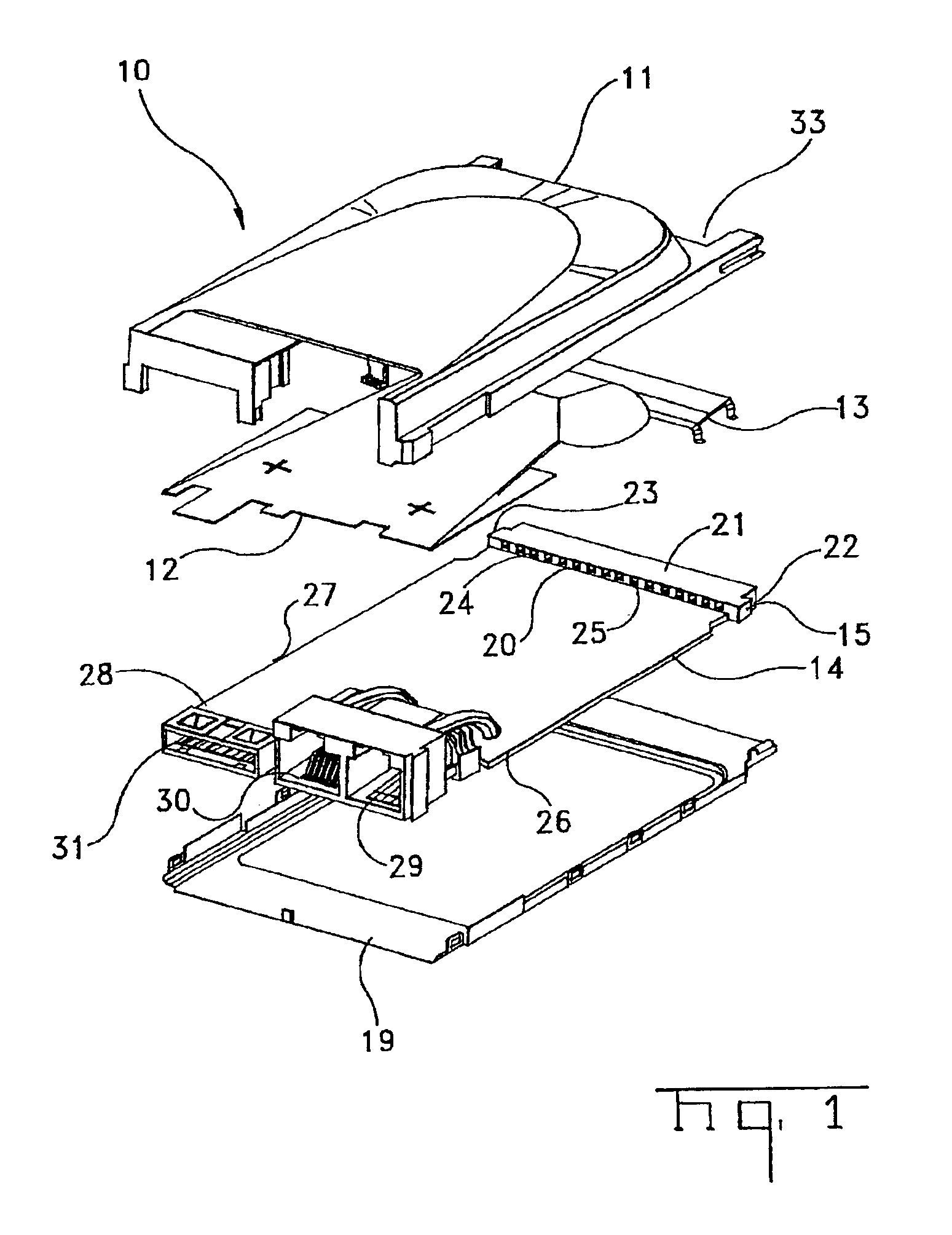
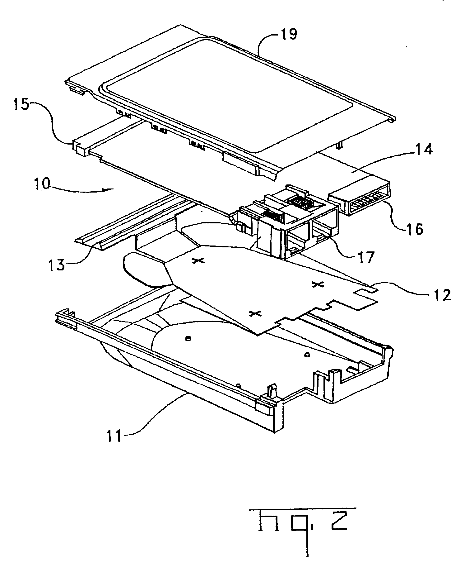
[0020]It will be evident to those skilled in the art that although the invention is described herein with reference to an Ethernet LAN (local area network) communications card conforming to certain PCMCIA size and interface standards, the invention can be applied to cards complying with other PCMCIA size and interface standards and performing other functions. For example, the card can serve as a local area network adaptor, voice mail device, a facsimile device, a modem or can combine LAN adapter and modem functions. Accordingly, the appended claims are not intended to be limited to PCMCIA cards of any specific form factor, interface or function. All of these devices are examples of those intended to come within the scope of the meaning of the term “communication devices” as used herein. Even further, other devices which require communication with one or more additional devices which are now available or which may become available in the future are intended also to come within the me...


PUM

PropertyMeasurementUnit
transmitting energyaaaaaaaaaa
ultrasonic energyaaaaaaaaaa
energyaaaaaaaaaa

Abstract

A process of manufacturing a card comprising: (a) placing a circuit board within a plastic panel and a metal panel, the metal panel having a plurality of tabs with barbs thereon, the plastic panel having one or more cavities adapted for receiving the tabs; (b) inserting the tabs within the one or more cavities; and (c) transmitting energy to the plastic around the tab such that the plastic flows at least partially around the barbs; and a card made from the above process.

Description

REFERENCE TO RELATED APPLICATIONS[0001]The present application is a continuation of application Ser. No. 09 / 678,519 filed on Oct. 3, 2000, now abandoned which in turn was based on and entitled to the priority of Provisional Application No. 60 / 172,399 filed on Dec. 17, 1999, both of which are incorporated herein by reference.FIELD OF THE INVENTION[0002]This invention relates to electronic communication devices. More particularly, the present invention relates to connectors used to attach a communications line to a computer.BACKGROUND OF THE INVENTION[0003]Many of today's computers, computer peripherals and other electronic products are designed to receive removable devices or cards, conforming to standards established by the Personal Computer Memory Card International Association (PCMCIA). These standards define the electrical and physical specifications of the card, including the interfaces between the card and the port or slot into which the card is inserted, as well as three card ...

Claims


Application Information

Patent Timeline
Patent Type & Authority Patents(United States)
IPC IPC(8): H05K5/02
CPCH05K5/0273Y10T29/49128Y10T29/49126
Inventor SIMMONS, RANDY GRAYPETERSON, KEVIN JOHN
Owner TE CONNECTIVITY CORP
Why Eureka
Try Eureka